
In 1967, there was a sudden collapse of the Silver Bridge, a pin-connected link suspension bridge over the Ohio River at Point Pleasant, West Virginia, that resulted in a loss of 46 lives. As a result, a 1968 federal act initiated a national bridge inspection program that recognized the need for periodic and consistent bridge inspections. The first National Bridge Inspection Standards (NBIS) were developed in 1971.
The 1983 failure of the Mianus River Bridge in Connecticut caused more concern related to fatigue and fracture critical bridges. This failure and further research resulted in mandated fracture critical bridge inspections.
Much has been learned in the field of bridge inspection, and a national Bridge Inspection Training program is now fully implemented. State and federal inspection efforts are more organized, better managed and much broader in scopes of work. The technology used to inspect and evaluate bridge members has significantly improved.
Fracture Critical Bridges
As specified in the National Bridge Inspection Standards (NBIS), Code of Federal Regulations (CFR) Title 23, PART 650, a fracture critical member (FCM) is “a steel member in tension, or with a tension element, whose failure would probably cause a portion of or the entire bridge to collapse.” Bridges that contain FCMs are defined as fracture critical (FC) bridges, and the Federal Highway Administration (FHWA) Bridge Inspector’s Reference Manual classifies FCMs as:
1) Steel girders in structural systems with up to two-girder (in California, three-girder) configuration
2) Tension members of steel trusses in structural systems with up to two-truss line (in California, three-truss line) configuration
3) Steel box girders with up to two-cell (in California, three-cell) configuration
4) Main suspension cables of suspension bridges
5) Steel hangers of suspension or arch bridges
6) Steel ties of tied arches or trusses
7) Pin-and-hanger assemblies (Figure 1) in structural systems with up to two girders or truss lines (in California, three girders/lines and pins shall also be tested ultrasonically)
8) Steel floor beams or cross girders
9) Steel bent subjected to tensile stress due to flexure
Also, moveable bridges and floating bridges are classified as FC bridges. California Department of Transportation (Caltrans) defines bridges with special fatigue prone details as special feature (SF) bridges.
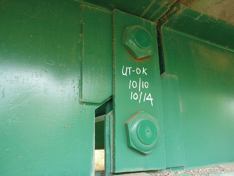
Figure 1. Pin-and-hanger assembly.
Inspection Procedures
A fracture critical bridge inspection is defined by the NBIS as a “hands-on” (i.e. within arm’s length of the component) inspection of fracture critical members. This type of inspection uses visual methods that may be supplemented by non-destructive testing (NDT). A detailed, visual, hands-on inspection is the primary technique of detecting cracks on steel tension members. Therefore, the inspection may require the bridge inspector to thoroughly clean critical areas before the inspection and use additional lighting and magnification. Other non-destructive testing methods (e.g. ultrasonic test, liquid dye penetrant test) may also be used to inspect the areas if the hands-on visual testing method is not sufficient to detect defects.
According to the NBIS, fracture critical bridges are required to be inspected at regular intervals not to exceed 24 months. Also, Caltrans mandates that special feature bridges be inspected at intervals not to exceed 48 months.
Because of the hands-on access requirement and the focus on specific bridge components, fracture critical bridge inspections are highly detailed and complex to plan and execute. The procedure can be described in three main steps: 1) preparing for the FC bridge inspection; 2) performing the FC bridge inspection; and 3) writing the FC bridge inspection report.
Preparing for the FC Bridge Inspection
The first step of FC bridge inspection preparation is to either develop the inspection plan (for an initial inspection) or to review the existing inspection plan (for subsequent inspections). The inspection plan should include:
- The bridge description
- FCMs and details that require inspection
- Location of the FCM’s on the bridge structure
- Inspection frequency
- Description of each inspection method (e.g. visual inspection, ultrasonic testing) applicable to the inspection
- Traffic management plan (e.g. lane closures, railroad flagging)
- Personal inspection equipment needed (e.g. flashlight, wire brush, nondestructive testing equipment)
- Access vehicles required for the inspection (e.g. aerial lift, under bridge inspection truck [UBIT], see Figure 2)
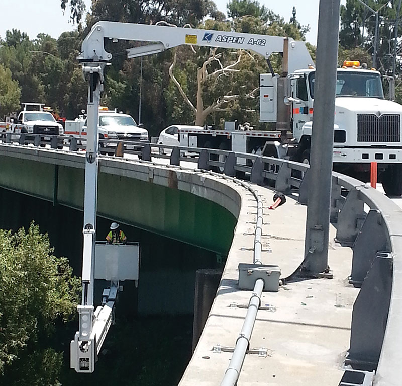
Figure 2. Under bridge inspection truck (UBIT).
Before the inspection, the inspector should review previous FC bridge inspection reports to familiarize himself with the structural element types, condition states, and recommendations related to FC steel members. Per inspection plan, the inspector submits a written request for flagging to the railroad company, and for traffic control and lane closures to the bridge maintenance crew. The final step of the FC bridge inspection preparation is the testing of all inspection equipment the day before the inspection.
Performing the FC Bridge Inspection
First, all participants of the bridge inspection meet at a time and location assigned by the FC bridge inspection team leader. Safety and the responsibilities of each member should be discussed during the meeting. In addition to the FC inspector, participants in an FC bridge inspection may include: 1) the UBIT operator or any other FC bridge inspector who drives the aerial truck during the inspection, 2) the traffic control team, and 3) the railroad flaggers if the bridge crosses railroad tracks.
Only after the traffic control team provides the required lane closures and the railroad flaggers inform the FC bridge inspector that entry into the railroad right of way is safe, the FC inspector can begin the inspection. Keep in mind that the FC bridge inspector should maintain continuous communication with the traffic control manager and the railroad flaggers to maintain a safe workplace throughout the duration of the bridge inspection.
The FC bridge inspector meticulously implements the inspection methods defined in the inspection plan. It is required that all existing cracks and deficiencies, which had been recorded in previous FC inspection reports, be carefully monitored. If an existing crack has propagated since the last inspection, then the new tip of the crack is punched to monitor any new growth during the next scheduled FC bridge inspection. If a new crack is found, the FC bridge inspector documents the crack details (i.e. length, location, and type of crack) on the bridge component where the crack is located, as well as in the FC bridge inspection report, supplemented by pictures of the crack.
Writing the FC Bridge Inspection Report
All FC bridge inspection findings are documented within the FC bridge inspection report. The report follows the standard format specified by the inspection agency. For example, based on the Caltrans standard, the main items included in an FC bridge inspection report are:
- Bridge identification information
- Name of FC bridge inspectors
- Date of inspection
- Access equipment used
- Traffic control team information
- Condition of existing cracks
- Description of new cracks
- Non-destructive testing (e.g. ultrasonic testing) results
- Supplementary pictures of the FC bridge inspection
Also, the FC bridge inspector may provide recommendations regarding critical findings (i.e. a structural or safety related deficiencies that require immediate follow-up inspection or action). If the critical findings need immediate attention, the FC bridge inspector should inform upper managers without delay.
Deficiencies
The most common deficiencies are:
- Fatigue cracks
- Fractures/dents due to impact loading
- Loss of cross section due to corrosion (e.g. pack rust)
- Misalignment of tension members
- Flaws in pin-and-hanger assemblies
Fatigue Crack Propagation
A fatigue crack occurs at a stress level below the yield stress and is due to repeated loading. This type of cracking can cause sudden and catastrophic failure of FC bridges. Fatigue cracks should be monitored during each FC bridge inspection cycle and, if a crack is showing continuous growth, the propagation should be stopped by drilling a hole at the crack tip. As shown in Figure 3a, a 5 mm fatigue crack growth on Girder 5 in Span 5 was found during an FC bridge inspection. To prevent further propagation of the crack, an arrest hole was drilled at the crack end. Before drilling, liquid dye penetrant testing was performed to locate the crack tip (Figure 3b). As shown in Figure 3c and 3d, a drilling machine was used to drill an arrest hole at the crack tip. The arrest hole stops the crack growth by releasing stresses at the crack tip. The bridge inspector will monitor the situation to see if the crack growth continues beyond the arrest hole during the next scheduled FC bridge inspections.
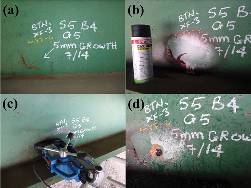
Figure 3. Fatigue crack arrest.
Pack Rust
Cross section loss of a steel girder due to pack rust corrosion is another defect that can be found in an FC bridge inspection. The pack rust occurs between two mating surfaces and is a volume of rust formed over the original steel. The pack rust may create localized distortion, and possibly cracking and loss of cross section.
Figure 4a and 4b shows 10 mm of pack rust that occurred between the bottom flange of the exterior steel girder and the bottom steel cover plate. As shown in Figure 4c, the pack rust between the bottom flange and the cover plate was removed during a painting project. Typically, caulking material is inserted into the cleaned areas to avoid further corrosion. Figure 4d shows the completed repair. These areas will be monitored for corrosion during the next FC bridge inspection cycles.
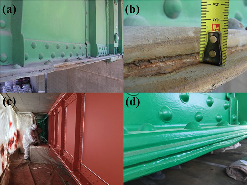
Figure 4. Pack rust corrosion.
Future Bridge Inspection Trends
In the future, bridge inspection may focus on the quantitative assessments of bridge performance and conditions. Certainly, bridge engineers will use an array of increasingly more sophisticated instruments, procedures, and systems to inspect the structures.
Using present technology, a variety of permanent sensors on bridges may collect critical performance data. These sensors will likely be powered by, and will report to, wireless networks. Data may be analyzed, and any flaw/deterioration will be detected automatically. Extensive use of sensors will also become possible as advances in the miniaturization of electronic devices, increased availability of wireless communications, and lower costs for devices and communication combine to provide an array of compact, permanent, inexpensive data acquisition systems.
Another advanced system that may assist bridge inspectors when performing an inspection of hard to reach locations and parts of any complex bridge will be the use of Unmanned Aerial Vehicles (UAVs). Using UAVs could help minimize risks associated with current bridge inspection methods, which include – but are not limited to – rope systems and special inspection vehicles. Extensive projects are underway to study the effectiveness of using UAVs to aid in bridge inspection work, typically in gathering images without the use of a UBIT and in areas where access is difficult or not safe for bridge inspectors. The increasing costs of bridge inspections are a concern for the Departments of Transportation in all states. The use of UAVs may help alleviate these costs and improve the quality of bridge inspections.▪