
Requirements of ACI 318-14
The American Concrete Institute (ACI) published the Building Code Requirements for Structural Concrete (ACI 318-14) and Commentary (ACI 318R-14) in the Fall of 2014. ACI 318-14 has been adopted by reference into the 2015 International Building Code (IBC). There are very significant organizational as well as technical changes between ACI 318-11 and ACI 318-14. A two-part article on the changes was published in the April and May 2016 issues of STRUCTURE magazine. A follow-up article on one of the most significant technical changes – the seismic design provisions for special (meaning specially detailed) shear walls – was published in the July 2016 issue. This is the last follow-up article on another critical change in the requirements for the confinement of columns in special moment frames of reinforced concrete.
Introduction to the Changes
The ability of the concrete core of a reinforced concrete column to sustain compressive strains tends to increase with confinement pressure. Compressive strains caused by lateral deformation are additive to the strains caused by the axial load. It follows that confinement reinforcement should be increased with the axial load to ensure consistent lateral deformation capacity. The dependence of the amount of required confinement on the magnitude of the axial load imposed on a column has been recognized by some codes from other countries (such as Canada’s CSA A23.3-14 and New Zealand’s NZS 3101-06) but was not reflected in ACI 318 through its 2011 edition.
The ability of confining steel to maintain core concrete integrity and increase deformation capacity is also related to the layout of the transverse and longitudinal reinforcement. Longitudinal reinforcement that is well distributed and laterally supported around the perimeter of a column core provides more effective confinement than a cage with larger, widely spaced longitudinal bars. Confinement effectiveness is a key parameter in determining the behavior of confined concrete (Mander et al. 1988) and has been incorporated in the CSA A23.3-14 equation for column confinement. ACI 318, through its 2011 edition, did not explicitly account for confinement effectiveness in determining the required amount of confinement. It instead assumed the same confinement effectiveness independent of how the reinforcement is distributed.
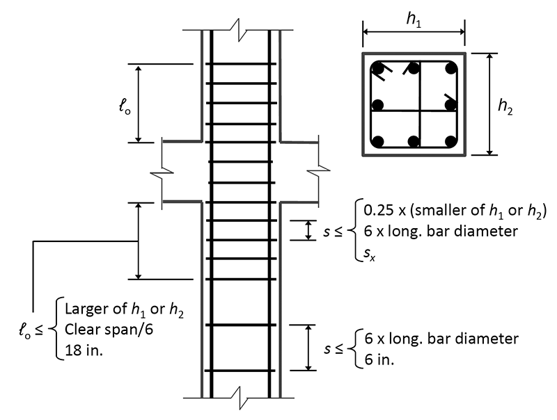
Figure 1. Confinement of rectangular column of special moment frame.
Given the above, confinement requirements for columns of special moment frames (Section 18.7.5, Figure 1), with high axial load (Pu > 0.3Ag f’c) or high concrete compressive strength (f’c > 10,000 psi) are significantly different in ACI 318-14. The following excerpt from Sheikh et al. explains why high-strength concrete columns are grouped with highly axially loaded columns:
“For the same amount of tie steel, the flexural ductility of HSC [High Strength Concrete] columns was significantly less than that of comparable NSC [Normal Strength Concrete] specimens tested under similar P/f’c Ag values. For the same percentage of the confining steel required by the ACI Building Code, NSC columns displayed better ductility than comparable HSC columns tested under similar P/f’c Ag. However, for the same level of axial load measured as a fraction of Po (the ultimate axial load capacity), HSC and NSC columns behaved similarly in terms of energy-absorption characteristics when the amount of tie steel in the columns was in proportion to the unconfined concrete strength. Conversely, the amount of confining steel required for a certain column performance appears to be proportional to the concrete strength as long as the applied axial load is measured in terms of Po rather than P/f’c Ag.”
The discussion below is about confinement over the length lo, the region of potential plastic hinging.
One important new requirement is as follows:
18.7.5.2 – Transverse reinforcement shall be in accordance with (a) through
(f)
Where Pu > 0.3Ag f’c or f’c > 10,000 psi in columns with rectilinear hoops, every longitudinal bar or bundle of bars around the perimeter of the column core shall have lateral support provided by the corner of a hoop or by a seismic hook, and the value of hx shall not exceed 8 in. (Figure 2). Pu shall be the largest value in compression consistent with factored load combinations including E.
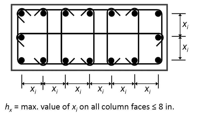
Figure 2. Confinement of high-strength or highly-axially-loaded rectangular column of special moment frame.
The change from prior practice is that instead of every other longitudinal bar having to be supported by a corner of a tie or a crosstie, every longitudinal bar will have to be supported when either the axial load on a column is high, or the compressive strength of the column concrete is high. Also, the hooks at both ends of a crosstie need to be 135-deg. As importantly or perhaps more importantly, the center-to-center spacing between laterally supported bars is restricted to a short 8 inches. In the absence of high-strength concrete or high axial loading, the maximum spacing goes up to 14 inches. In ACI 318-11 and prior editions, the 14-inch limitation used to apply to the center-to-center spacing between legs of hoops and crossties.
The other new requirement is in the following section:
18.7.5.4 – Amount of transverse reinforcement shall be in accordance with Table 18.7.5.4 (reproduced here as Table 1).
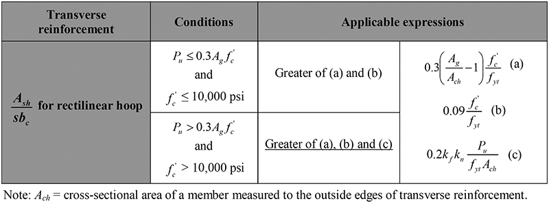
Table 1. (ACI 318-14 Table 18.7.5.4). Confinement of high-strength or highly-axially-loaded rectangular column of special moment frame.
The concrete strength factor, kf , and confinement effectiveness factor, kn, are calculated by (a) and (b).
kf = [pmath]{f prime_c}/{25,000}[/pmath] + 0.6 ≥ 1.0 (18.7.5.4a)
kn = [pmath]{n_l}/{n_l – 2}[/pmath] (18.7.5.4b)
Where nl is the number of longitudinal bars or bar bundles around the perimeter of a column core with rectilinear hoops that are laterally supported by the corner of hoops or by seismic hooks. See Tables 2 and 3 for values of kf and kn, respectively, calculated by the above formulas.
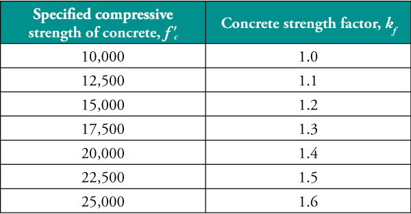
Table 2. Values of concrete strength factor, kf .
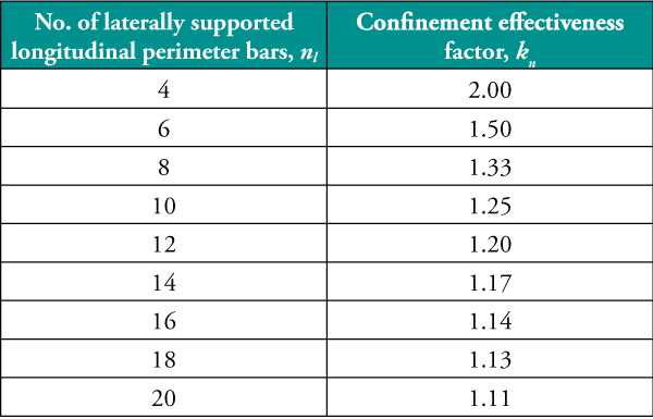
Table 3. Values of confinement effectiveness factor, kn.
Impact of Changed Confinement Requirements
As is seen above, for columns that are made of concrete with specified compressive strength, f’c, exceeding 10,000 psi and/or are subject to factored axial force, Pu, exceeding 0.3Ag f’c (Ag = gross cross-sectional area), the required confinement over regions of potential plastic hinging (typically at the two ends) is now a function of the axial force. The impact of the changed requirements is assessed in Table 4.

Table 4. Impact of the changed confinement requirements of ACI 318-14 for the regions of potential plastic hinging of special moment frame columns.
Bars larger than No. 6 in size are not very practical for use as transverse reinforcement. Also, the ensemble of one hoop and crossties in two orthogonal directions has a thickness of 2¼ inches for No. 6 bar size, which translates into a 1¾-inch clear spacing for a 4-inch center-to-center spacing. Thus, Table 4 shows the limitations on sustainable axial load as the specified compressive strength goes beyond 6 ksi. The limitations have become significantly more severe under ACI 318-14. It should be noted that ACI 318 does not allow Pu to exceed 0.8 (accidental eccentricity factor) x 0.65 (φ for columns with discrete transverse reinforcement) x Po = 0.525 Po, where
Po = Ag f’c + Ast (fy – f’c)
So, 0.5 f’c Ag is an extremely high axial load level, which is unlikely to be encountered in special moment frame columns. Also, if one needs to go beyond the range of factored axial loads and concrete strengths that can be accommodated with No. 6 transverse reinforcement at a reasonable spacing, the most effective solution is to switch to transverse reinforcement with yield strength, fyt, higher than 60 ksi. ACI 318 allows fyt to be up to 100 ksi.
Conclusions
This article discusses the modified ACI 318-14 confinement requirements for columns of special moment frames. It is shown that the modified requirements have a significant impact on columns that are highly axially loaded (Pu > 0.3Ag f’c) or made of high-strength concrete (f’c > 10,000 psi) or both.▪
Acknowledgments
Grateful acknowledgments are due to Pro Dasgupta and Ali Hajihashemi of S. K. Ghosh Associates Inc. for their considerable help with the paper.
Notation
Ach = cross-sectional area of a member measured to the outside edges of transverse reinforcement
Ash = total cross-sectional area of transverse reinforcement, including crossties, within spacing s and perpendicular to dimension bc
Ast = total area of non-prestressed longitudinal reinforcement
bc = cross-sectional dimension of member core measured to the outside edges of the transverse reinforcement composing area Ash
f’c = specified compressive strength of concrete
fy = specified yield strength for non-prestressed reinforcement
fyt = specified yield strength of transverse reinforcement
h1 = plan dimension of column in one of two orthogonal directions
h2 = plan dimension of column in other orthogonal direction
hx = maximum center-to-center spacing of longitudinal bars laterally supported by corners of crossties or hoop legs around the perimeter of the column
kf = concrete strength factor
kn = confinement effectiveness factor
ℓo = length, measured from joint face along axis of member, over which special transverse reinforcement must be provided
nl = number of longitudinal bars around the perimeter of a column core with rectilinear hoops that are laterally supported by the corner of hoops or by seismic hooks
P = axial force
Po = nominal axial strength at zero eccentricity
Pu = factored axial force
s = center-to-center spacing of transverse reinforcement
xi = dimension from centerline to centerline of legs of hoops or crossties (ACI 318-14), of laterally supported longitudinal bars (ACI 318-14)
Portions of this article were originally published in the PCI Journal (March/April 2016), and this extended version is reprinted with permission.
References
ACI (American Concrete Institute) Committee 318, Building Code Requirements for Structural Concrete (ACI 318-14) and Commentary (ACI 318R-14), Farmington Hills, MI, 2014.
ICC (International Code Council), International Building Code. Washington, DC, 2015.
CSA (Canadian Standards Association), Design of Concrete Structures (CSA A23.3-14), Etobicoke, Ontario, Canada, 2014.
Standards New Zealand, Concrete Structures Standard (NZS 3101: Part 1: 2006) and Concrete Structures Standard – Commentary (NZS 3101: Part 2: 2006), Wellington, New Zealand, 2006.
Mander, J. B., Priestley, M. J. N., and R. Park, R., “Theoretical Stress-Strain Model for Confined Concrete.” Journal of Structural Engineering, Vol. 114, No. 8, 1988, pp. 1804–1825.
Sheikh, S. A., Shah, D.V., and Khoury, S. S., “Confinement of High-Strength Concrete Columns,” ACI Structural Journal, V. 91, No. 1, January – February 1994, pp. 100-111.