
In the May 2016 issue of STRUCTURE, Part 1 of this series addressed through-bolts in masonry walls. That article was based on hybrid masonry research funded by the National Science Foundation’s Network for Earthquake Engineering Simulation Research (NEESR), but the information provided is useful to all designers of masonry construction where through-bolts are useful. The goal of this article is to further help practitioners gain a better understanding of the behavior of three particular types of connectors; these are hybrid “link” and “fuse” connectors, as well as headed stud anchors. While the “link” and “fuse” connectors are specific to hybrid masonry, the headed stud anchors are not.
Hybrid Masonry Overview
Refer to the Part 1 article for an overview of hybrid masonry. The system is composed of a structural steel frame and reinforced concrete masonry panels. Hybrid Masonry offers a design alternative to braced frames and moment-resisting frames that is appropriate for low and mid-rise construction. It is best suited for projects where a structural steel framing system and masonry walls would naturally be chosen due to structural and architectural efficiency.
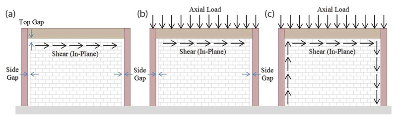
Figure 1. Hybrid masonry systems: (a) Type I; (b) Type II; (c) Type III.
Figure 1 shows, graphically, the three distinct types of hybrid masonry. In Type I hybrid masonry (Figure 1a), steel connectors transfer in-plane shear between the steel frame and the top of the masonry panel. These connectors can be either rigid “link” plates or ductile “fuse” plates. The connectors do not transfer any vertical load to the masonry wall, but their design can have a significant influence on the overall performance of the system. This particular situation makes the wall design a non-loading bearing shear wall.
In Type II and III hybrid masonry (Figure 1b and 1c), headed studs are used to transfer shear from the beam and/or columns to the masonry panel. Vertical load is also transferred directly through contact from the beam to the top of the masonry panel. This instance makes the wall design a load bearing shear wall.
Type I Connections
As mentioned, the steel connector plates used in Type I Hybrid Masonry can be designed either as elastic “link” connectors or as ductile “fuse” connectors. In both cases, the intent is for the connector plates to transfer only lateral and in-plane shear from the steel frame to the top of each concrete masonry panel. “Link” connectors are designed to remain elastic during a design level seismic event, while the concrete masonry wall is designed with sufficient ductility to absorb the necessary lateral displacement during the earthquake. Post-earthquake repair will likely require replacement of some of the ductile masonry walls.
Ductile “fuse” connectors are designed to remain elastic during wind and low seismic events, but to yield and provide hysteretic energy absorption during moderate to high seismic events. Fuses which are tapered to provide an equal potential for yielding along a significant length of the connector provide the best energy dissipating behavior. These fuses provide a high degree of ductility to the system. The masonry wall is designed with an appropriate overstrength factor so that it remains essentially undamaged during the earthquake. Post-earthquake repair will involve only the replacement of damaged fuses.
The tapered ductile fuse design was one of the several prototypes initially evaluated using cyclic quasi-static testing of individual fuses. To study the behavioral effects of simultaneously loading multiple fuses, wall tests using both four and six tapered ductile fuses to transfer the load were conducted. Figure 2 compares the hysteretic response of the wall test using six fuses with hysteretic responses of other tests using one or four fuses. The loads were scaled, as indicated, to facilitate a direct comparison.
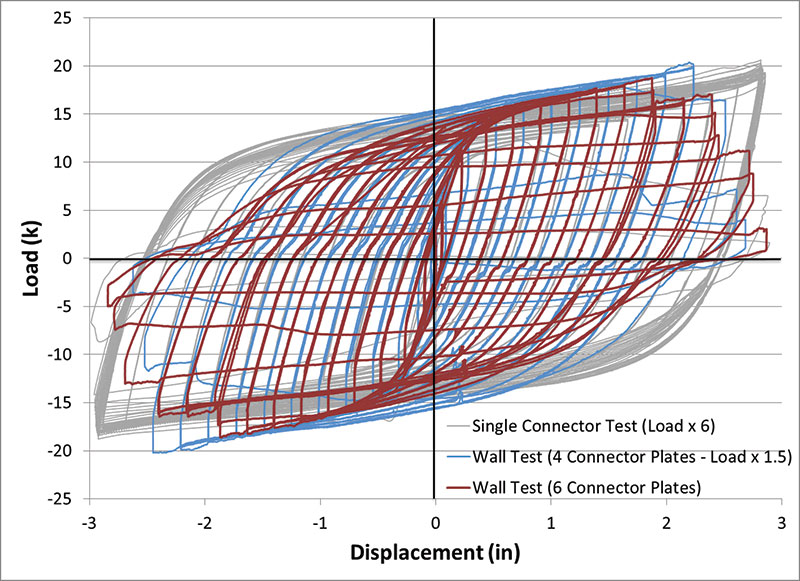
Figure 2. Hysteretic responses for tapered ductile fuse connectors (1k = 4.448kN, 1in = 25.4mm).
Steel Connector Plate Attachment
Several fuse and link plate configurations were considered and tested as part of the NEESR project on hybrid masonry. The original concept of a bent plate welded to the bottom flange of the steel beam, as shown in Figure 3, showed an undesirable non-ductile weld failure (Goodnight et al., 2011). A second bent plate configuration shown in Figure 4 proved more successful at transferring the large shear loads from steel frame to masonry panel. A third alternative developed was to weld side plates to the flanges of the steel beam and then either bolt (with slip critical bolts) or weld the fuse or link plates to these side plates as shown in Figure 5 (Ozaki-Train et al., 2011). The advantage of the bolted configuration is the ease of fuse replacement after a damaging seismic event.
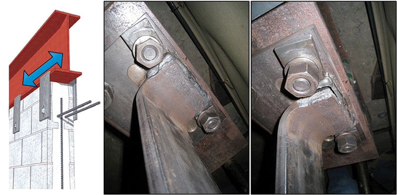
Figure 3. Original bent plate concept with non-ductile weld failure mechanism. Courtesy of International Masonry Institute, www.imiweb.org.
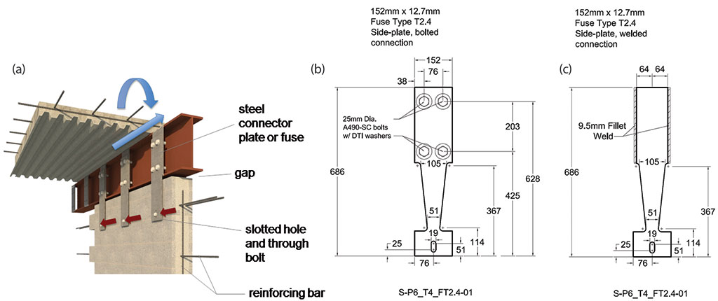
Figure 5. Link connectors (a) or ductile fuse connectors (b) and (c) attached-to-beam side plates using slip critical bolts or welds (Dimensions in mm; 1mm = 0.0394 in). Figure 5a courtesy of International Masonry Institute, www.imiweb.org.
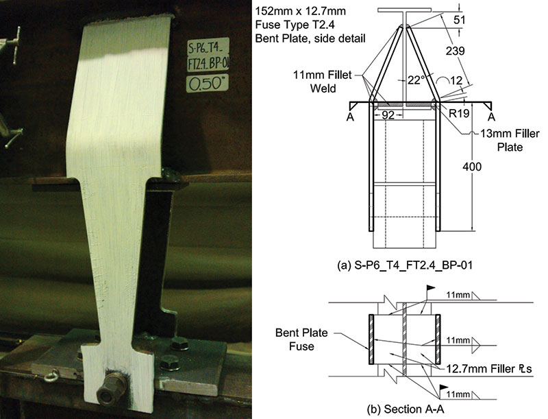
Figure 4. Successful bent welded fuse connector plates on either side of beam to masonry panel connection.
For each of these connectors to function correctly, it is essential that the through-bolt connection between the masonry panel and the fuse or link plate can transfer the required load without premature failure. The through-bolts were discussed in Part 1.
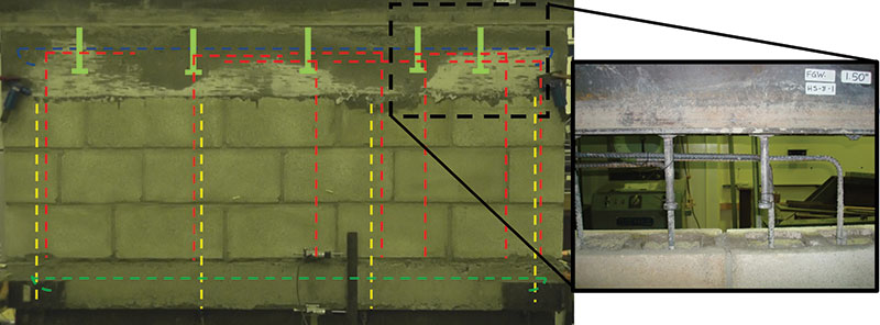
Figure 6. Hybrid masonry type II test wall showing the location of reinforcement and headed studs.
Type II Connections
Type II hybrid masonry requires a connection between the steel beam and the top of the concrete masonry panel that transfers both in-plane shear and vertical load. One approach to achieving this load transfer is the use of headed studs welded to the bottom flange of the steel beam and embedded in a grout beam at the top of the masonry wall (Figure 6 and 7). Figure 7 shows the test setup used to conduct cyclic quasi-static loading tests on the Type II connections made with headed studs. Non-linear behavior is restricted to the ductile masonry panel, so the headed stud connection should be designed for elastic response using an appropriate overstrength factor.
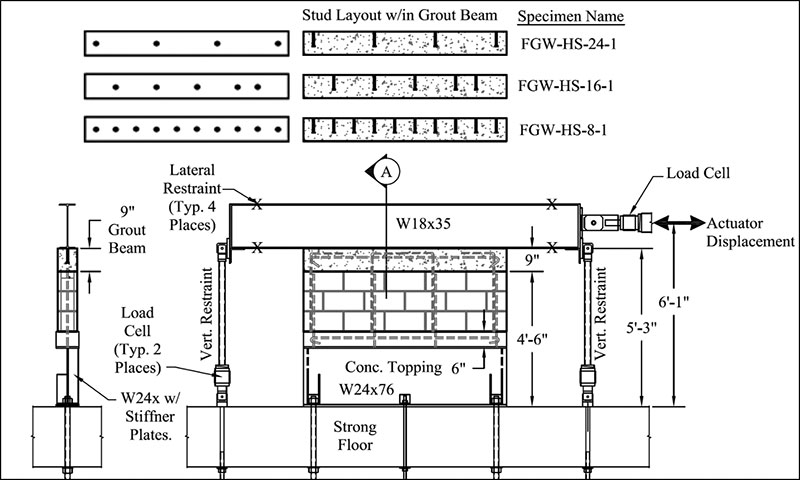
Figure 7. Type II headed stud connection testing setup.
Headed Studs Embedded in a Grout Beam
The American Institute of Steel Construction’s (AISC) 360-10 provides design guidance for the use of headed studs to transfer load for composite structural steel beams and columns. Headed stud embedment in a grout beam at the top of a CMU wall is the primary load transfer mechanism for Type II hybrid masonry systems. Limited testing was conducted to observe local failure mechanisms associated with the load transfer from the steel beams through headed studs, the grout beam, and into the top course of a CMU wall. Three tests were conducted to verify if the AISC specifications were valid for this case. Details regarding the reinforcement and testing protocol were documented in a research report and paper at the 12th NAMC (Aoki and Robertson, 2013; Aoki et al. 2012; Johnson and Robertson 2015).
The results were compared with the AISC 360-10 provisions as well as code specified limit states from TMS 402-13 (The Masonry Society) and ACI 318-14 (American Concrete Institute). The TMS 402-13 limit states of masonry breakout at anchors, masonry crushing at anchors, bearing, and shear and ACI 318-14 limit state of shear loading of anchors were considered. The AISC headed stud specification, and limitations, as described in the commentary, are summarized below.
AISC 360-10 Section I8.2a Shear Studs specifies the in-plane shear transfer capacity for studs embedded in solid or composite slabs. This section is not intended for use when there is an edge in the vicinity of the studs unless concrete breakout in shear can be prevented by confinement (AISC 2010) – there is no specific guidance to determine if there is sufficient confinement.
Qn = 0.5Asa[pmath]sqrt{f’_c E_c}[/pmath] ≤ RgRpAsaFu
For the hybrid masonry case, the grout beam was formed using the grout which filled the CMU. The grout compressive strength was tested in accordance with ASTM C1019 and used in place of f’cin the AISC equations including the calculation of Ec. The AISC equation predicts a nominal capacity of 21.5 kips based on the shear studs (right hand side of the inequality), which was less than 28.5 kips that AISC predicts based on the capacity of the grout (left hand side of the inequality). Table 1 indicates the AISC predicted total capacity of the headed stud connection based on grout failure, stud failure as well as the maximum experimental load, and the average experimental load per stud.
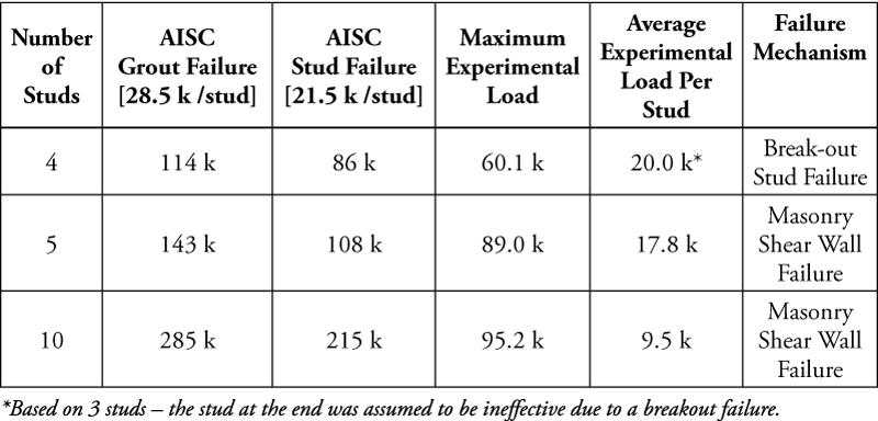
Table 1. AISC headed stud capacity.
A user note in AISC Section I8.3 states that the provisions are not intended for hybrid construction where the steel and concrete are not working compositely, such as with embed plates (AISC 2010). The section accounts for steel anchor failure and concrete breakout in shear. Geometric limitations of the studs are formulated to preclude anchor pry out and concrete breakout in tension. The commentary states, “…if these provisions are to be used, it is important that the engineer deem that a concrete breakout failure mode in shear is directly avoided through having the edges perpendicular to the line of force supported, and the edges parallel to the line of force sufficiently distant that concrete breakout through a side edge is not deemed viable… the determination of whether breakout failure in the concrete is a viable failure mode for the stud anchor is left to the engineer. Alternatively, the provisions call for required anchor reinforcement with provisions comparable to those of ACI 318 [for anchors]” (AISC 2010).
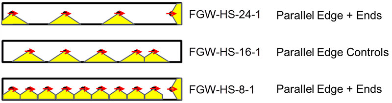
Figure 8. Assumed geometry applied to the ACI 318 shear loading of anchors provisions.
Applying anchor shear loading provisions of ACI 318 results in breakout failures shown in Figure 8. The figure is a cross-section through the length of the wall specimens. The circles show the locations of the studs. The concrete which is assumed to breakout is also shown. Note that in-plane loading results in breakout of the concrete at the parallel edge. Table 2 shows the ACI and TMS predictions controlled by the breakout of anchors compared with the maximum experimental loads. The ACI 318 provisions are conservative, while the TMS provisions overestimate the capacity of the specimen with 4 studs, which failed at the grout beam and appeared to be initiated at the headed studs. The other two specimens failed within the CMU wall after the load was transferred through the headed stud connection. The authors suspect that the high average force required of each stud caused the breakout type failure for the specimen with 4 studs, and the lower average force per stud precluded a stud initiated failure for the specimens with more studs. Figure 9 shows the breakout and splitting failure of the grout beam with 4 studs.
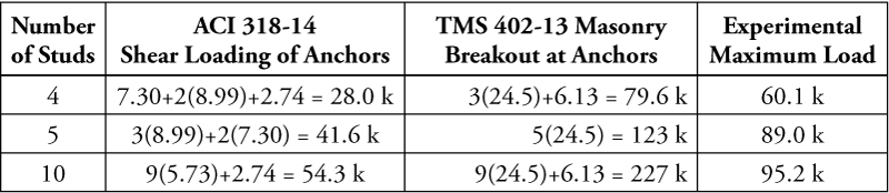
Table 2. ACI318 and TMS 402 breakout predictions for headed studs.
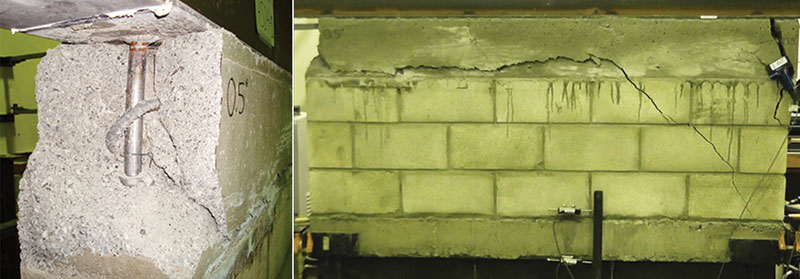
Figure 9. Breakout failure of test specimen with 4 headed studs.
Conclusions
Practitioners who would like to use connection details described in this article will not be able to find code language or limit states that directly address the behavior, boundary conditions, and loading which can make these connections cost effective for hybrid masonry systems. They will need to rely on engineering judgment and should consider the following information.
Steel Connecter Plates & Fuses
- Welded connections commonly used in conjunction with bent plates attached to the bottom flange of W sections, to provide lateral restraint at the top of masonry walls, should not be used to transfer shear forces parallel to the wall. The C-shaped weld is required to resist shear, torsion, and flexure. The AISC Manual does not provide tabulated capacities for this case. Even weld analysis by the instantaneous center of rotation method or elastic method may not provide conservative capacities considering the relatively large deformations within the bend of the plate that are immediately adjacent to the beginning of the weld.
- Details which eliminate the 90-degree bend in the plate and transfer the loads directly to either the top flange or web of the beam can provide the restraint and capacity needed to transfer in-plane shear loads.
- Highly ductile fuses can be designed to limit the force transferred through these connections, thereby reducing damage to the masonry panels. Regions of equal potential for yielding within the fuse are critical to achieving a ductile response.
Use of Headed Studs Embedded in a Grout Beam
- Do not count on the full capacity of the stud as documented in AISC 360-10, which is intended for shear transfer from a beam into a slab which provides significant lateral confinement to the concrete in the vicinity of the shear stud. Indeed, the AISC commentary expresses the importance of using a design which precludes a breakout failure as defined by ACI 318.
- TMS 402-13 anchor related limit states do not account for the thin geometry of the grout beam detail and resulted in unconservative predictions of failure load for the limited number of tests reported here.
- ACI 318-14 shear loading of anchor bolts limit states provide a conservative estimate of the capacity.
- Too few tests with headed stud failures are available to make any code change recommendations. However, observed failures indicate that the following details are good practice to reduce the potential for early break-out failure of the grout beam.
- Headed studs should be placed at least 12 inches (305mm) from the end of the CMU.
- Headed studs should be placed in the center of the grout beam to provide maximum edge distance to each side of the grout beam.▪
REFERENCES
Abrams, D.P. (2011), “NSF NEESR Research on Hybrid Masonry Seismic Structural Systems,” Proceedings of 11th North American Masonry Conference, Minneapolis, MN, June 2011.
ACI Committee 318, 2014. Building Code Requirements for Structural Concrete (ACI 318-14) and Commentary, Farmington Hills, MI: American Concrete Institute.
AISC 2010, Specifications for Structural Steel Buildings, AISC 360-10, American Institute of Steel Construction, Chicago, IL. 2010.
Aoki, J. and Robertson, I.N., Dec. 2012 “Hybrid Masonry Connector Plate and Headed Stud Small-scale Wall Testing”, Research Report UHM/CEE/12-06, University of Hawaii at Manoa.
Aoki, J., and Robertson, I.N., Johnson, G.P., “Strength and Behavior of Steel-to-Masonry Connectors,” Proceedings of the 12th Canadian Masonry Symposium, Vancouver, BC, June 2-5, 2013.
Asselin, R.E., Fahnestock, L.A., Abrams, D.P., Robertson, I.N., Ozaki-Train, R., Mitsuyuki, S., (2012) “Behavior and Design of Fuse-Based Hybrid Masonry Seismic Structural Systems”, Proceedings of 15th World Conference on Earthquake Engineering, Lisbon, Portugal, September.
Asselin, R.E., Fahnestock, L.A., and Biggs, D. (2013) “Design of Hybrid Masonry Systems”, Proceedings of the 2013 Structures Congress, Pittsburgh, PA.
Biggs, D.T., (2007) “Hybrid Masonry Structures,” Proceedings of 10th North American Masonry Conference, St. Louis, Missouri, June.
Biggs, D.T., (2011) “Bracing Steel Frames with Hybrid Masonry,” Proceedings of 11th North American Masonry Conference, Minneapolis, MN, June.
Biggs, D.T., (2013) “Hybrid Masonry Design and Construction Practices,” Proceedings of 12th Canadian Masonry Symposium, June.
Goodnight, S., Johnson, G.P., and Robertson, I.N., May 2011, “Connector Development for Hybrid Masonry Seismic Structural Systems”, Research Report UHM/CEE/11-03, University of Hawaii at Manoa.
Johnson, G., Robertson, I.N., Goodnight, S., Ozaki-Train, R., (2011) “Behavior Of Energy Dissipating Connectors & Fuses”, Proceedings of 11th North American Masonry Conference, Minneapolis, MN, June.
Johnson, G.P., Robertson, I.N. (2015) “Behavior of Headed Stud Connections to CMU Shear Walls” Proceedings of 12th North American Masonry Conference, Denver, CO, May.
Ozaki-Train, R., Johnson, G.P., and Robertson, I.N., Dec. 2011, “Hybrid Masonry Connector Development, Phase II”, Research Report UHM/CEE/11-04, University of Hawaii at Manoa.
Robertson, I., Johnson, G., Mitsuyuki, S., and Aoki, J. (2013). Ductile Fuse Connectors for Hybrid Masonry Systems, Proceedings of the 2013 Structures Congress, Pittsburgh, May.
TMS, 2013. Building Code Requirements and Specifications for Masonry Structures, Masonry Standard Joint Committee TMS 402-13 /ACI 530-13 /ASCE5-13, ed., Boulder, CO., The Masonry Society.