
475 Fifth Avenue is an existing building near Bryant Park at the intersection of 41st Street and Fifth Avenue in New York City. The 24-story, 1920s era building recently underwent a major renovation that required structural engineering designs to support the building’s architectural elements and to accommodate changes to the mechanical system. The structural scope for the project included strengthening the second-level flooring system for retail loading; framing of new mechanical penthouse; framing of new floor and wall openings to accommodate MEP ductwork and louvers; framing of new canopy, new stair crossover and closing abandoned shafts and openings. One challenging aspect of the project was to remove an existing column between Levels 1 and 2 located in the middle of the redesigned lobby (Figure 1). This column removal is the primary focus of this article.
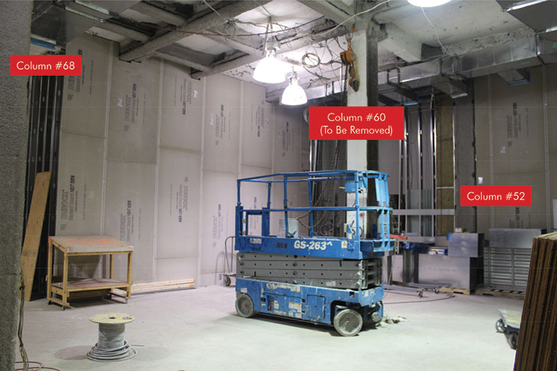
Figure 1
The building’s structural system is a steel moment frame. The gravity system consists of a cinder concrete topping slab over a wire mesh reinforced concrete slab supported by steel beams spanning between girders. The girders are connected to the columns in both directions with moment connections, to resist lateral loads. All existing shear and moment connections were riveted, as is typical for buildings of this age. The original structural drawings for the building were unavailable, so all information necessary for design was obtained in the field.
Exploratory Phase
Since no structural drawings existed, DeSimone performed exhaustive exploratory work, including structural probes, walkthroughs, and field measurements. Structural steel coupon tests revealed the steel to be weldable and that it had a yield strength close to that of ASTM A36 steel. Concrete density tests were performed to determine the weight of the existing floor system, which was 110 lbs/ft3.
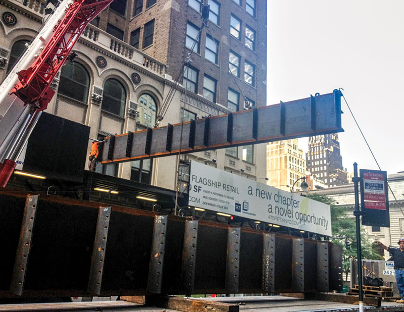
Figure 2
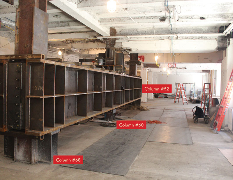
Figure 3
Analysis and Design of Transfer System
Figure 1 indicates the portion of the frame where the column (labeled as column #60) is to be removed between the first and second floors. The spacing between columns was approximately 18 feet. A transfer girder was designed to span 36 feet to support the weight of the 23 floors above column #60 and transfer the load to the adjacent supporting columns (numbered #52 and #68). Based on the exploratory work, service gravity loads carried by each of the columns was estimated. The transfer girder was designed to be supported at Level 2 to maintain the floor-to-floor height at the ground floor lobby. For ease of delivery and rigging, the transfer girder was designed as back-to-back built-up channels. The individual channel members were delivered into the building through a window on Level 2 (Figure 2). They were connected using stiffener plates and cross bracing at the top and bottom (Figures 3 and 4). The supporting columns were cover-plated to increase their capacity to support the additional load. Bearing and supporting brackets were designed to be welded directly to the columns to transfer the load to the girder. Existing footings (concrete piers) for column #52 and #68 were found to have enough reserve capacity to support the additional load increase. However, lean concrete was poured around the top of the piers to increase confinement of the existing concrete at the point of load transfer. Finite element analysis, including an Eigenvalue buckling assessment, was performed to check stresses and the susceptibility to buckling of the transfer girder and supporting columns (Figure 5).
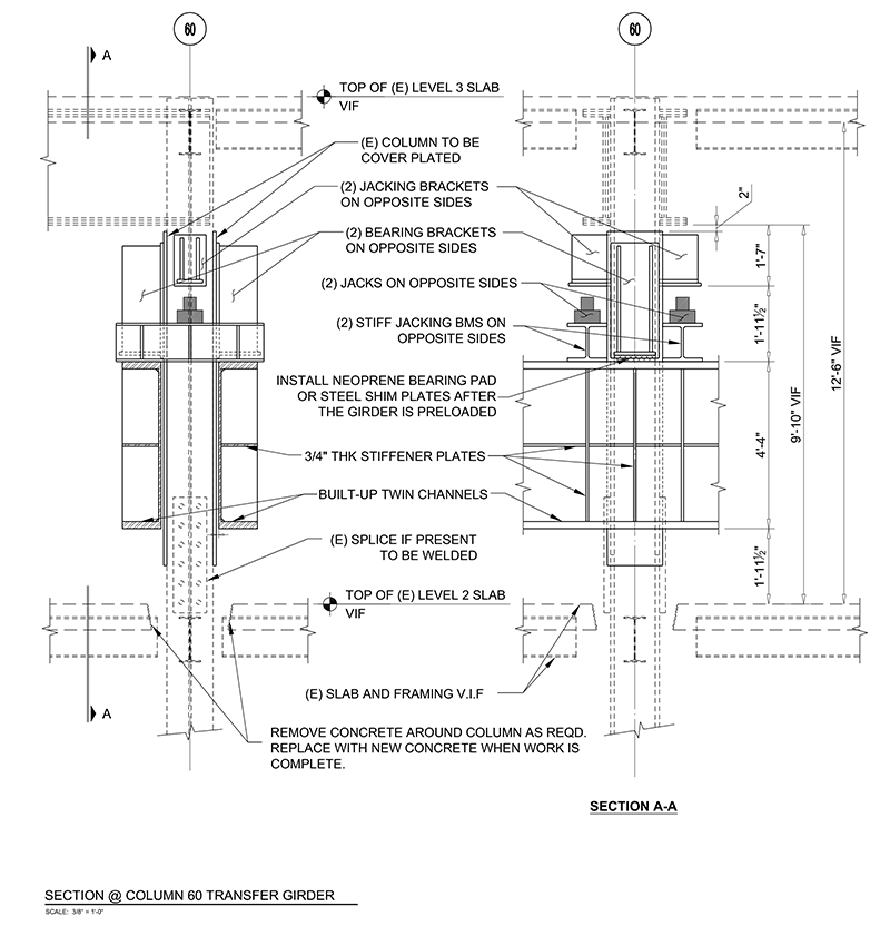
Figure 4
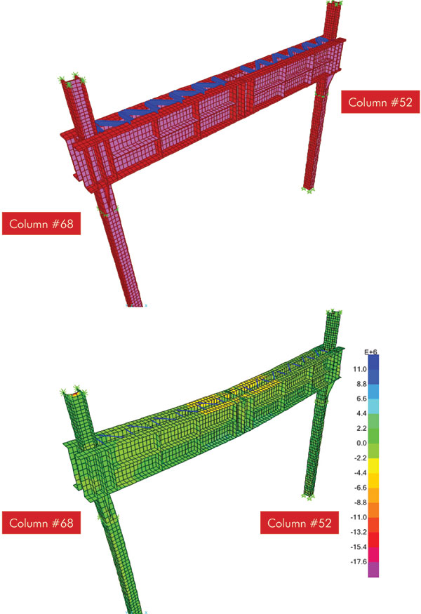
Figure 5
Preloading Approach to Column Removal
In a conventional column removal, a transfer girder is installed and connected to the supporting columns. Then the column to be removed is attached to the transfer girder and cut below the girder. As illustrated in Figure 6, the transfer girder is loaded instantaneously from an undeformed state. This condition causes the girder and its supported levels to undergo deflection, instantaneously leading to potential serviceability issues such as cracks in the concrete floor, finishes, and partitions.
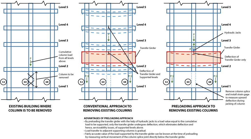
Figure 6
To counteract potential problems with the conventional approach, DeSimone employed an innovative preloading method to transfer the column load. The transfer girder was preloaded using hydraulic jacks to a load value equal to the service dead load supported by the column to-be-removed (column #60). This preload imposes an initial dead load deflection on the girder. Figure 4 shows details of this approach. First, two pairs of brackets are welded onto column #60, a pair of bearing brackets transfer the load from the column onto the transfer girder, and a pair of brackets are used for jacking (Figure 7). A small gap was left directly below the bearing brackets to ensure that all the load during the preloading operation goes into the jacking brackets and that the bearing brackets are not engaged. The existing column splice for column #60 between Levels 1 and 2 was removed and strain gages were installed, at the splice, to monitor the vertical movement of the column during the jacking operation. The transfer girder was gradually preloaded to the service dead load value, or until vertical movement at the splice was detected by the strain gages. The hydraulic jacks were then locked and shim plates were introduced to close the gap between the bearing brackets and the transfer girder. Once the shim plates were in place, the hydraulic jacks were removed, thereby disengaging the jacking brackets and transferring the load to bearing brackets. This process allowed for column #60 to be cut between Level 1 and 2. This preloading approach to column removal has several advantages over the conventional approach. The primary advantage is that only the transfer girder undergoes deflection and the supported floors are unaffected, causing no serviceability issues on the supported levels. The finished lobby space without the existing column #60 is shown in Figure 8.
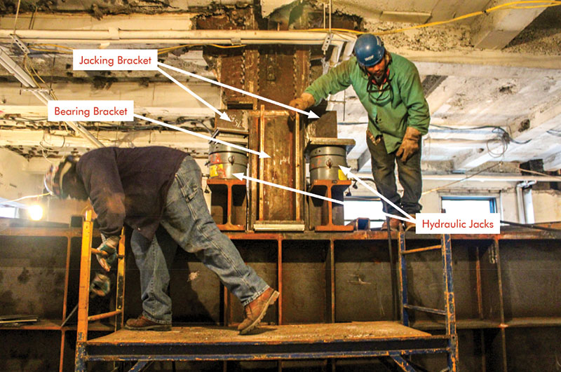
Figure 7
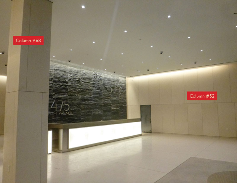
Figure 8
Conclusion
DeSimone successfully removed the column from the ground floor of an existing 24-story building using an innovative preloading approach. This approach helped minimize serviceability problems that are common in such projects.▪