
Software programs for structural engineers continue to escalate in complexity, as engineers become increasingly reliant on those tools to increase accuracy in analysis and efficiency during design. To solve complex problems efficiently, and to gain a more in-depth understanding of the elements being analyzed, structural engineers are using Finite Element Analysis (FEA). Of course, each of the different FEA programs has their idiosyncrasies, all of which require designers to pay close attention when using these programs.
What exactly is finite element analysis? It is the process of reducing (simplifying) a problem with infinite degrees of freedom to a finite number of elements with unique material properties. FEA programs can resolve even the most complex problems in a reasonable amount of time. The process of finite element modeling and analysis is an approximate solution which closely mimics an actual structure in a way that allows structural engineers to design for the stresses, forces, and deflections that are determined using the FEA method.
Some of the more commonly used software programs for FEA with masonry design are RAM Elements (soon to be released as STAAD(X) from Bentley Systems, Inc.), as well as RISA Floor and RISA 3D (from RISA Technologies). Other FEA programs with high-end analysis features, such as SCIA Engineer, are important tools for structural engineers because they offer more options for creating elements that more closely represent a structural component’s behavior.
General Comments about Finite Element Modeling
Finite element models are created by modeling line, plate/shell, and solid (or brick) elements, with associated end nodes.
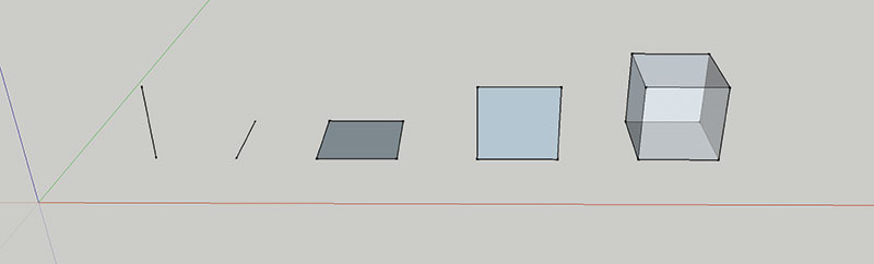
Line elements. | Plate/shell elements. | Solid (brick) element.
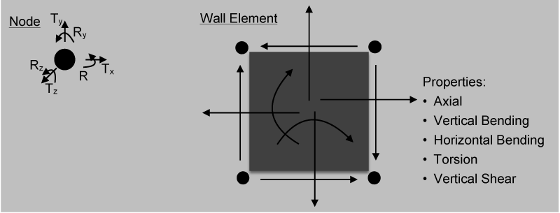
Node degrees of freedom and wall element properties.
Complicated three-dimensional elements, such as solid (or brick) elements, are not usually available in most commercial design software. In structural engineering, most problems can be modeled with one-dimensional line elements, or two-dimensional plate or shell elements, and result in reasonably accurate solutions. When creating a model, the line and plate/shell elements with their associated properties are defined, and the end nodes are defined with translational or rotational degrees of freedom. The properties assigned to the line and plate elements must be defined to associate a reasonable stiffness with each element. Columns and beams (not masonry lintels) can be modeled with line elements, and walls and slabs can be modeled with plate/shell elements. Many software programs allow you to define the geometric boundaries of entire wall panels from movement joint to movement joint (a movement joint is either an expansion joint in brick or control joint in concrete masonry) and discretize those large geometries into smaller finite elements by a process called meshing. Sometimes meshing is a manual process, and other times software programs will offer automatic meshing.
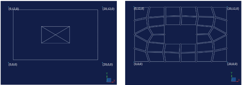
Wall Geometry with opening. | Wall discretized into finite elements example of automatic meshing from RAM Elements.
Pre-Processing and Masonry Modeling
Many of the analysis procedures used today assume thin plate theory and linear elastic behavior for the plate elements. The elasticity of the material is described by a stress-strain curve, which shows the relationship between internal force per unit area and the relative deformation. Linear elasticity is a simplification, assuming linear relationships between the components of stress and strain. This simplification is valid only for stress states that do not produce yielding or fracture. Reinforced masonry and reinforced concrete elements are not linearly elastic because once a concrete element cracks, steel reinforcement is engaged. Of course, masonry is made up of several different components which closely mimic this behavior when it is reinforced.
Many times, finite element software provides element modification factors to account for the reduced stiffness of the masonry or concrete element once it has cracked. In some programs this factor is automatically applied, sometimes it must be manually defined, and in others, it is not an option. Some programs offer multiple element modification factors including bending in each direction, torsion, shear, and axial deformations. The engineer must confirm that the element modification factor in the program accounts for the reduced stiffness from cracking and only applies to the bending stiffness in the direction of the cracked behavior, and is not used with the shear stiffness or the axial stiffness of the element.
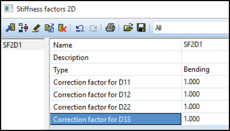
Example of bending modification factors available in SCIA Engineer.
When the analysis program does not have an appropriate element modification factor, an adjustment to the actual properties of the element might be necessary. An adjustment may mean modifying the elastic modulus of the element. The elastic modulus is used to determine the stiffness for the element in each of the deformation categories. Therefore, an adjustment will impact the element in all properties of bending, shear, and axial deformation. This type of modification must be used with caution, and may not always be appropriate.
Masonry is unique in that it is often reinforced in the vertical direction, but unreinforced in the horizontal direction. Therefore, the element may only span horizontally if it remains uncracked in that direction. If the anticipated design demand stresses are beyond the allowed cracking stresses, the engineer should consider reducing stiffness by using a reduced element modification factor. Again, this emphasizes the need for the modification factors to be considered separately in each orthogonal direction. When all of the factors are equal, the slab element behaves as an isotropic material, a material having the same properties in all directions. When the factors are different from each other, the slab elements behave as orthotropic materials, having different properties along three perpendicular axes.
Caution is prudent when using stiffness factors. With certain combinations of factors, the structure can become unstable and the results can become unreliable. Also, the interaction of the stiffness factors may be more complex than it appears upon first inspection.
Masonry design also requires custom material types be used to account for attributes that are unique to the material, such as grouting only reinforced cells (partial grouting). Partial grouting affects both the loading aspect (from the self-weight contribution) of the finite element model, as well as the stiffness of the masonry finite elements. There are some programs, such as RISA 3D, which account for partial grouting of the masonry wall. For programs that do not, modifications must be made to the finite element properties (such as altering the thickness of the element).
There are advantages and disadvantages associated with modifying the thickness of an element to accommodate for the actual condition of partially-grouted masonry. The axial and shear stiffness of the wall may be accurately modified; however, the reduction to the bending stiffness of the finite elements would not be accurate and result in elements that are much weaker than they are in a real partially-grouted wall. Therefore, engineering judgment must be used when the software does not account for partial grouting, and the engineer is required to make modifications which may bring unintended consequences. It is also important to recognize that overall geometric wall modeling for masonry walls must account for the physical separation between walls due to control joints. RAM Elements allows for quickly separating linked wall panels (panels that share end nodes) into separate wall panels with unique end nodes. Whether there is a tool to create this separation, or the walls are manually modeled separately with unique end nodes, separation in the finite element model is required to ensure each wall can act independently.
There are a few items to consider regarding finite element meshing. Finite element programs are based on plate elements that are quadrilateral (four nodes per plate/shell), and the ideal shape is a square. Without going into the theory of why this is ideal, it is important to know that the further plate/shell elements are from a square, the less accurate the finite element approximations become. When considering the ideal size of the plate/shell elements when meshing a wall geometry (manually or by auto meshing), the designer must consider the accuracy of the results, computational processing time, and the material being modeled. When considering accuracy, the finer the mesh (smaller plates/shells and more of them) the higher the probability that the elements will be square. This is especially true in complex models. However, the smaller the mesh, the more plate/shells and nodes, and larger the demand for computation. Even with the advances in software, finite element models with a very fine mesh can result in unreasonable computational times.
Lastly, consideration should be made for material properties. It could be argued that masonry and concrete have an inherent minimum element size due to what is referred to as the “chunkiness” of concrete. It is unreasonable to have differential movement between nodes that are closer together than the thickness of the masonry element. This is similar to evaluating one-way shear no closer than the depth of element away from a support. Considering all of these size recommendations, there is also the point of diminishing return. When a model’s approximate solution starts to converge, using a finer mesh doesn’t result in any significant changes to the final solution. In general, the recommended maximum plate/shell size would be the span distance divided by ten and the minimum plate size should be no less than the thickness of the masonry wall. For example, a twelve-inch thick, thirty-foot tall wall would have a minimum plate size of twelve inches and a maximum plate size of three feet [span/eight]. Of course, there may be unique situations when these guidelines must be re-evaluated but, in general, they have been found to be a good starting point for determining plate/shell size in finite element models for walls.
Care should be exercised when modeling masonry wall systems with finite element analysis programs to ensure all of the boundary conditions, the stiffness of the elements, and weights of the elements are accurately accounted for in the development of the finite element model.
Some may wonder if it is worth this amount of effort for a masonry wall. It is necessary if the engineer wants to understand the true behavior of complex wall systems, such as in-plane shear wall capacity of perforated shear walls (wall panels with openings in the middle), and gain an even better understanding of the out-of-plane behavior in walls with openings. Of course, modeling masonry finite elements is also essential in the following lateral analysis scenarios:
- Lateral dynamic analysis for any building with masonry lateral-resisting elements. Appropriate load and stiffness is required to understand the true dynamic behavior, which yields building fundamental periods.
- Lateral analysis load distribution (through rigid or semi-rigid diaphragms) between masonry and other systems or materials, such as concrete or structural steel frames.
Post-processing and Design
The next challenge involves taking the results from the finite element model and analysis and converting them into information that can be compared to code-defined maximum stresses or forces that determine the capacity of the masonry wall. Finite element programs for masonry combine the results of several plate/shell elements within geometric areas or strips of the model, as defined by the user. Areas above openings are rationalized into an area that will be checked against lintel capacities. Engineers must study software programs and the combination (summation) of finite element results, and make modifications when necessary.
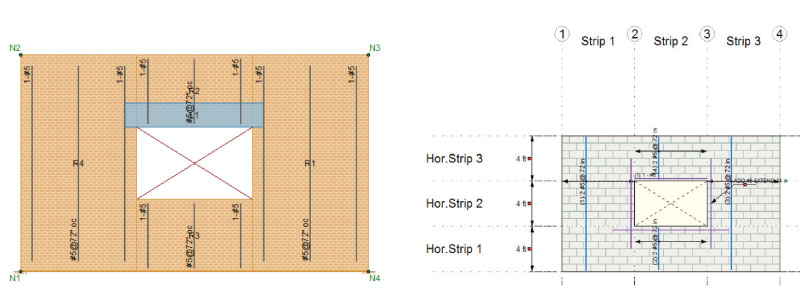
Image from RISA showing wall areas, image to the right of RAM Elements showing wall strips.
Generally, structural engineering software will check for in-plane bending and shear capacity, out-of-plane bending and shear capacity, and axial capacity of masonry walls. Lintel shear and bending capacities must also be evaluated. Lintels (not in a finite element model) have traditionally been checked by assuming a simply supported “beam” element. Finite element approximation and design of the area above the openings are fundamentally different, as the plates/shells in this area are interlocked by sharing nodes with the other surrounding elements of the wall. When evaluating bending moment in walls, software programs often evaluate only vertical bending and do not evaluate horizontal bending and shear. Therefore, the engineer is left to manually check the horizontal bending moment against an unreinforced masonry bending capacity. If horizontal bond beams are used within a masonry wall, the horizontal bending moment may be manually checked against the allowable bending capacity of a reinforced element.
Some software programs may or may not be able to correctly define the finite element model. If it does not, the designer must decide if manual modifications can be made to the model without adversely affecting other attributes and the results. Further, evaluation of the post-processing design features of programs and design checks show that programs are not always complete, and must be supplemented with manual checks of the analysis results. Ultimately, careful evaluation when selecting software that is best suited for the scenario at hand is required. Supplementing with additional calculations may be needed. Therefore, it is recommended the engineer thoroughly review the element response to applied forces. The simplest and most revealing check can be made by animating the deflections of the elements. For example, a simply supported wall element should have a deflected animated shape that is a simple curve, and a wall with moments fixed at the top or with a parapet (cantilevered element above the roof) should have a compound curved. To review the forces in the element, a quick manual calculation should be within 20-25% of the anticipated forces in any particular element within a finite element model. Lastly, reviewing the reactions to the applied forces is a good study to make sure the elements have been modeled properly.
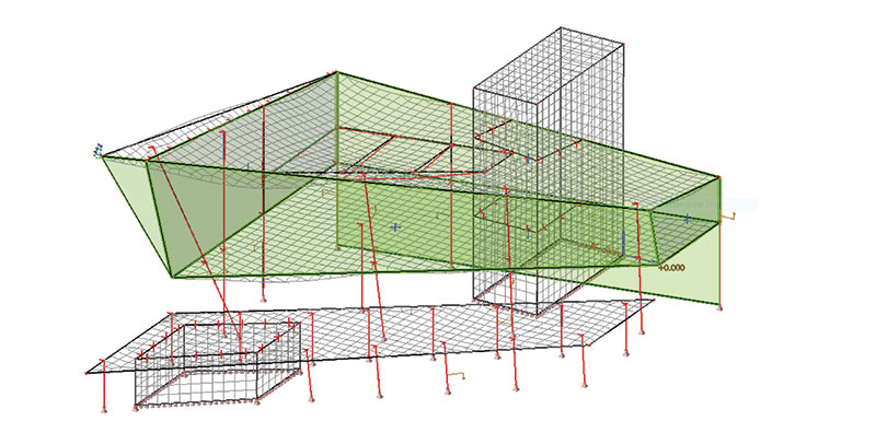
Example of complete finite element model with masonry walls, which has concrete slabs, steel beams connecting to the walls (model from SCIA Engineer).
The finite element models structural engineers create often contain other materials and elements that connect to the masonry wall elements. It is important to consider how those elements connect to the masonry. Areas to watch for include: Should the beams (line elements) framing into the wall be modeled as pinned or fixed? Should the end of the beam be offset from the centerline of the masonry wall panel to model eccentricities? Are the shell/plate slab elements pinned or fixed to the masonry walls?
There are many items to consider when using FEA software programs to model masonry walls. However, there are very good software options available which make using FEA programs more accurate and more efficient, and make us better engineers once we learn how to use them correctly.▪