
Recent fatalities associated with failed structural building elements have generated discussion about actual causation and whether building code changes are required. These failures have also increased the demand for architectural and structural inspections on similar existing elements.
The authors are consultants who frequently forensically diagnose alleged construction defect claims. Clients are typically developers, designers, contractors, insurance agencies, attorneys, manufacturers or building owners. This background provides a unique perspective on the relative risk to the structural engineer.
Although the structural engineer usually does not specify the exterior envelope, the potential for alleged liability remains at locations where structural elements interface with and/or penetrate the exterior building envelope. Engineers have a primary responsibility to protect public safety, so understanding the goals, methods, and potential problems with the building envelope at decks and other structural appendages can allow them to be part of the solution and perhaps limit their liability exposure.
This article will primarily discuss balconies, decks, and stairways, but the issues are similar for other structural and non-structural appendages as well.
Recent Failures
The two most recent structural failures involving exposed exterior elements (EEEs), both with resultant loss-of-life, involved multi-residential wood light-frame construction. The first was an exterior cantilevered balcony in Berkeley, California. The second was an exterior stairway in Folsom, California. Although the various forensic investigations (by others) into these tragic failures are ongoing, media images depict conditions associated with wood decay related to severely damaged structural components and unintended water intrusion.
The Berkeley tragedy involved a cantilevered system that had limited redundancy in the vertical load path. Obviously, material degradation to a structural member in a low redundancy system can lead to exactly these types of catastrophic failures. In response, the Structural Engineers Association of California (SEAOC) wrote to the California Building Standards Commission (CBSC) with respect to the California Building Code and the California Residential Code. In an attempt to provide improvements, the letter recommended the following multi-pronged approach:
1) Review water barrier requirements.
2) Review ventilation requirements.
3) Consider introducing requirements to improve the durability of EEE’s structural members where the structural members are concealed.
The problem will not be an easy one to resolve, since it is a very complicated issue involving many disciplines with overlapping levels of responsibility.
The Decay Problem
In light-frame wood structures, deterioration is primarily caused by long-term excessive moisture trapped within concealed spaces. Decay requires a food source (the wood) for fungi, and the presence of oxygen and moisture. Fungi and oxygen are always present, so moisture is the ingredient that can most easily be mitigated. The moisture sources can vary across different climate zones.
The most common condition that leads to long-term excessive moisture exposure is building envelope leakage. The author’s experience shows that structural appendages and their supports exposed to excessive moisture without drying usually, but not always, exhibit some form of visual indicator prior to a change in structural performance (i.e. failure).
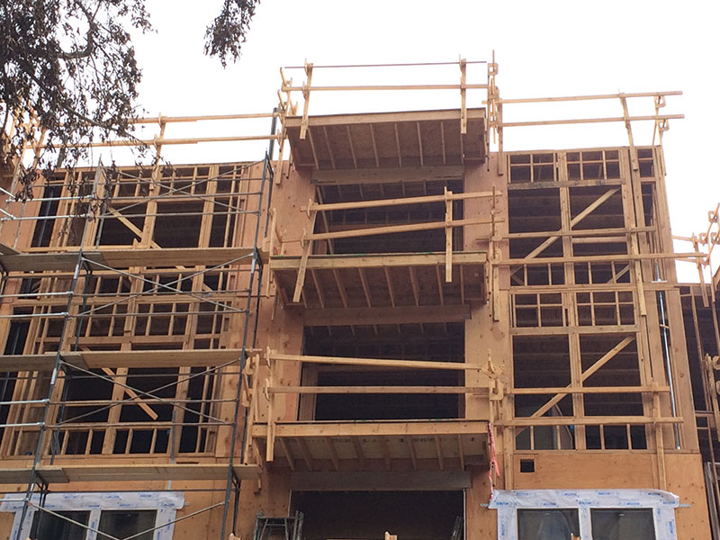
Figure 1. Common wood balcony configuration under construction.
A typical California wood balcony, under construction, is shown in Figure 1. Non-treated Douglas-fir lumber joists are designed to cantilever outward from the interior of the building (as extensions of the floor framing), passing through the exterior wall. Ideally, all of the wood is protected by waterproofing and any water on the surface of the deck drains away. In a perfect world, the structural engineer designs the framing, the envelope designer (usually the architect) designs the waterproofing and the contractor builds it so there is never a leak.
Fundamentals of Waterproofing
Newer building envelope design embraces the “four Ds”.
Deflection – Simply means that an effective way to keep the structure dry is to deflect the water away.
Drainage – To the extent that water contacts the building, plan on a managed drainage path. Similar to a complete load path, a proper drainage path is pivotal.
Drying – To the extent that portions of the building do get wet, allow them to dry. A key part of drying is ventilation.
Durability – In the event that prolonged periods of wetness are unavoidable, use durable materials.
The tip for the structural engineer is to be cognizant of what the envelope designer is trying to achieve. Then the engineer can evaluate if their structural design is part of the solution or part of the problem.
Leaks often occur when the four Ds are not addressed; where water is not deflected, the drainage path is interrupted and there is limited ventilation to allow for evaporation of the water that has worked its way through the building envelope.
Waterproofing on vertical walls is similar, but with a very steep slope. Cladding deflects water; a drainage plane allows water behind the cladding to drain and provides air flow for ventilation and drying.
Entry Points for Water
Building envelope leakage at EEEs can be from one or more of the following sources:
a) flashing details at a horizontal waterproofing system
b) flashing details at guardrail and/or handrail assemblies
c) flashing details around fenestrations such as doors and windows
d) flashing details around penetrations
e) a combination of some or all of the above
Horizontal waterproofing membranes are low-slope, or near-horizontal, systems that rely on a complete integration to perform. Think of it as a complete load path. Most membranes are either a sheet-good or fluid-applied. The membranes typically adhere to sheet metal shaped to create flashing at corners, edges, scuppers, drains, etc.
Even though these membranes are characterized as “waterproof”, most rely on water draining away in relatively short periods of time (days rather than weeks). Standing water on membranes can prematurely deteriorate the membrane and or “sweat through” to the substrates. This is why slope and drainage provisions are critical.
The important takeaway point is that it is not just low-slope waterproofing systems that leak and cause structural damage, but that adjacent walls and fenestrations are frequent contributors to damage as well.
Requirements of the International Building Code
The following are requirements in the 2012 IBC concerning waterproofing. There is no single section of the code that addresses all of the issues, and many sections default to manufacturer’s instructions.
Chapter 15 of the 2012 IBC addresses slope in the requirements for roof coverings but does not explicitly include waterproofed surfaces of decks and balconies. Balconies and decks can be covered by the requirements of Chapter 15 by applying the definition for rooftop structures of “a structure on top of any part of a building”. Since this is critical to waterproofing performance, this is an issue worthy of a potential code change.
Chapter 14 of the 2012 IBC contains requirements for exterior wall weather protection performance, essentially that it must prevent the accumulation of water within the wall assembly and provide a means of draining water to the exterior. Section 1405.4 requires flashing to be installed in such a manner so as to prevent moisture from entering the wall or to redirect it to the exterior. This is obviously a performance-based provision. It also focuses exclusively on details at specific locations, which is consistent with what is found in forensic investigation practice.
It has been, and continues to be widely accepted that it is beyond the structural engineer’s scope to anticipate and design for defective “as-built” building envelope construction. Section CB.5 of the Commentary in the 2002 version of ASCE 7 stated this understanding as, “Water infiltration through poorly constructed or maintained wall or roof cladding is considered beyond the realm of designing for damage tolerance.”
Chapter 23, Section 2304.11 of the 2012 IBC addresses the protection of wood against decay. The presence of an impermeable moisture barrier generally meets the requirements for protection against decay. The recent failures and the potential risk to life safety warrant reevaluating and perhaps strengthening these requirements. Perhaps the inclusion of a drainage plane and/or sloping of the impermeable moisture barrier, in addition to the mere presence, are worthy of inclusion.
Proper Design and Plan Review
As noted above, the design of the waterproofing system is generally in the architectural scope, not the scope of the structural engineer. Compounding the problem, the waterproofing system gets far less attention in design, plan review and construction than it deserves, on a relative risk basis, compared to other parts of a project.
In the author’s experience, waterproofed balconies and other appendages are treated by plan checkers as roofs with respect to applicable slope and drainage provisions, in the absence of detailed product ICC Evaluation Reports. In reality, each waterproofing system has an ICC Evaluation Report that mandates minimum slope and drainage requirements (typically 2%). Creating a consistently proper slope within the actual waterproofing systems is uncommon. The membranes typically follow the slope of the structural framing substrate.
Finally, most membrane manufacturers have requirements for what is considered an acceptable substrate. If the membrane is being placed directly on a structural element such as structural sheathing, asking the designer of the waterproofing system if he or she is specifying a product compatible with the structural material could go a long way to avoiding lawsuits or even injury to occupants resulting from the decayed structural member that can follow a failed membrane.
Lessons to be Learned
Slope Considerations
Figure 2 depicts a typical exterior deck-to-wall detail. The membrane is located on the top of the wood sheathing, beneath the concrete topping and turned up the vertical surface to lap beneath the metal pan flashing.
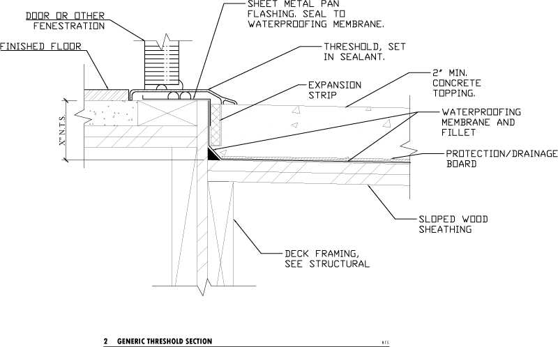
Figure 2. Generic detail.
The detail graphically depicts sloped structural wood framing, the wood sheathing, and the concrete topping. The detail also refers the contractor to the structural drawings for the deck framing. These notes could be interpreted as transferring the reader’s attention to those portions of the drawings prepared by the responsible party (which is would be incorrect in almost all instances) or transferring responsibility for computing framing slopes/elevations/clearances on the exterior deck to the structural engineer (which the structural engineer would object to). For many modern light-frame apartment complexes, the drainage design can be a complex exercise which cannot be addressed with simple notes on the architectural drawings or hoping that the structural engineer has somehow dealt with the issue.
Note also how the concrete topping is specified as “2-inch min”; the implication being that the topping can be thicker as needed. But the fixed dimension from the threshold to the top of the structural elements limits the ability to slope the topping by thickening the topping. Inadequate slope of the concrete topping fails to provide Deflection, the first ‘D’. The dimension on the left is “not to scale”, resulting in a detail that makes it look much easier to achieve the minimum thickness and slope than it really is.
This detail also specifies a protection/drainage board over the membrane to protect the membrane from damage during the placement of the concrete topping and other construction activities, as well as to provide a drainage plane. Providing the slope for drainage, the second ‘D’, at the membrane is important as water will work its way beneath the concrete topping.
This detail could easily be constructed with level structural framing if the structural drawings don’t show the required slope and a flat or nearly flat concrete topping due to dimensional restrictions. This detail does not show the configuration of the cantilevered wood joists. However, cantilevering a level floor joist out past the exterior of the building requires specific structural detailing to produce a sloped structure on the cantilever. A cantilevered joist system also results in no elevation change of the structure across the threshold, requiring a different solution for matching finished elevation. The bottom line is that elevations, clearances and surface slopes must all be coordinated by the building envelope (and waterproofing) designer, which is typically not the structural engineer.
In harsher climates where the freeze thaw cycle is a concern, drainage and drying become even more paramount. Water that is not drained away from the building can saturate concrete and masonry resulting in very rapid deterioration.
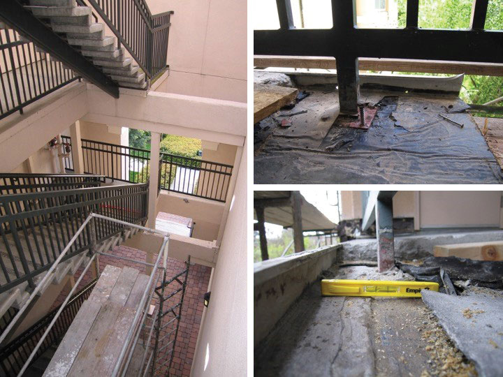
Figure 3. Detail creates a reverse slope.
Figure 3 shows a condition where the details at the edge of the concrete topping created a reverse slope in the membrane interrupting the second ‘D’, the drainage path to the weep holes. This stairwell is exterior of the building envelope and exposed to rain, similar to a covered balcony. The buildup of layers of materials, notably the closure plate for the concrete topping, cause the membrane to change slope at the edge of the stairwell. This situation is perhaps a little more difficult for the structural engineer to anticipate and influence in design, but it is certainly something to look for during design coordination phase and during structural observation site visits.
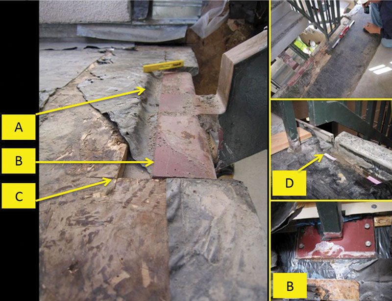
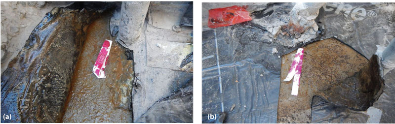
Figure 4. Failed waterproofing at elevated stairway.
Smooth Surfaces
Figure 4 (page 24) depicts an elevated stairway exposed as part of an investigation associated with litigation. The stairs were comprised of steel stringers and pre-cast concrete treads. The guardrails were comprised of steel pickets lag-screwed into the supporting wood framing. The waterproofing membrane and concrete topping system was conceptually intended to emulate a “bird-bath” with perimeter weep-holes intended to drain water reaching the membrane level. It was discovered that the waterproofing design and installation fell well below the performance standard of providing positive drainage to prevent ponding and preventing moisture from penetrating the building envelope.
Issues observed within Figure 4 include:
A) Inadequate slope to drain, the second ‘D’. Areas of “reverse-slope”.
B) Waterproofing traverses rough/sharp edges.
C) Horizontal OSB notched for steel plate. Water directed behind cladding.
D) Waterproofing spans dissimilar materials.
Without adequate waterproofing, the supporting structural element was exposed to excessive amounts of moisture. The actual waterproof design coordinator of record (The Architect) was apparently unaware of the myriad of “as-built” changes and errors.
All the details pointed out above are issues the structural engineer should be aware of and represent opportunities for the structural details to help in the waterproofing solution.
Figures 5a and 5b. Penetrations.
Penetrations
Appendages are the intersection of the interior and exterior, and as such require some elements to cross the moisture barrier. Penetrations such as those shown in Figures 5a and 5b (page 24) occur in both the vertical barrier on the wall and horizontal barrier on the surface of the appendage. Penetrations may be unavoidable, but they can be reduced and located and designed strategically to better integrate with the waterproofing system. Providing Deflection and Drainage (the first and second Ds) to direct water away from penetrations is the first line of defense at penetrations. Providing Drying and Durability (the third and fourth Ds) can go a long way toward mitigating minor, intermittent water intrusions and prolong the life of the structure.
Multi-ply Members
Members built up of multiple plies can trap moisture between the plies. The exterior of the member can appear in generally good condition while the interior begins to resemble a hollowed out log.
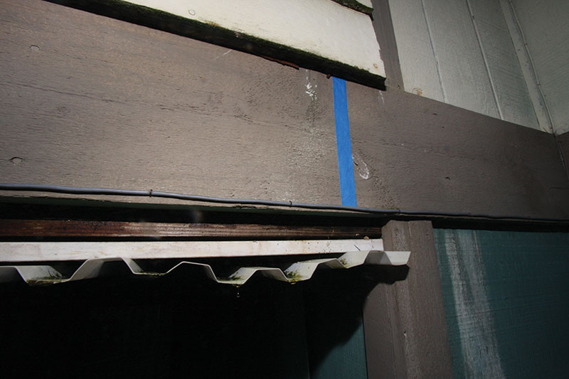
Figure 6. Fascia board over edge-beam.
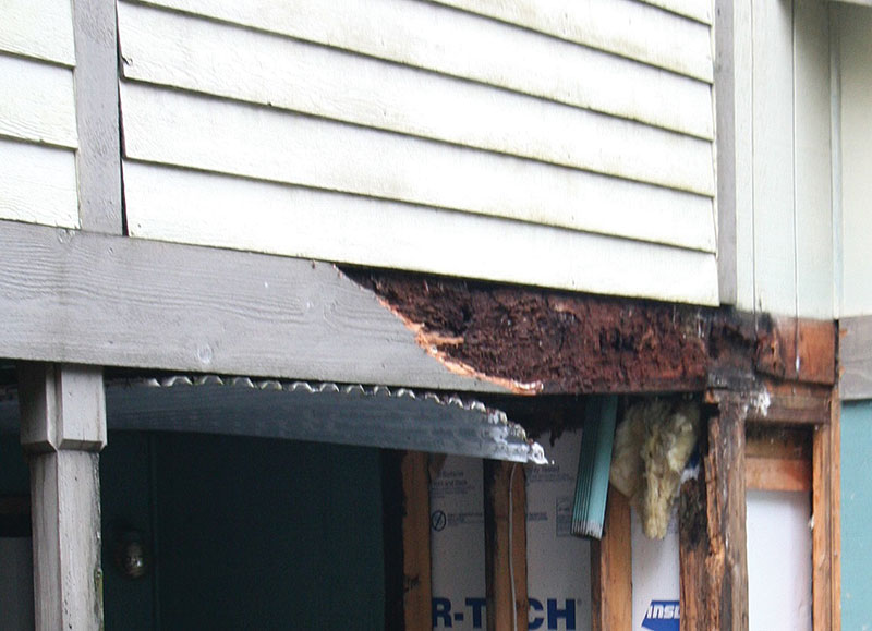
Figure 7. Structural framing (fascia removed from assembly shown in Figure 6).
Figure 6 show a fascia board over the face of a multi-ply edge beam at the edge of a deck and Figure 7 shows the structural framing once the fascia has been removed. Further investigation revealed similar concealed deterioration between the plies of the beam. This deck was not waterproofed, but it illustrates how multi-ply elements can trap moisture and conceal damage. Using a single, solid structural member is a more durable solution that eliminates the faying surface that traps moisture between the plies. Adding vertically oriented spacers that provide a drainage space between the fascia and the beam could have significantly improved the performance of this deck.
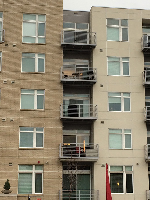
Figure 8. Steel balconies.
Materials
Why not just use steel? Figure 8 shows steel balconies in Colorado. The setback of the exterior walls allows for a structural framing system alternate to cantilevering of the interior floor joists. The choice of material is the fourth ‘D’, durability.
However, to highlight that steel is not a panacea and the difficulty of integrating structural appendages, Figure 9 depicts a pre-fabricated steel stair tower bolted to a wood-frame building. The project requirements featured mock-ups, quality-control inspections, coordinated design and a specialty waterproofing consultant, yet this element failed to perform. The openings created by coped structural connections provided a path for water to access the interiors of the elements. The structural engineer can’t blame that on the architect.
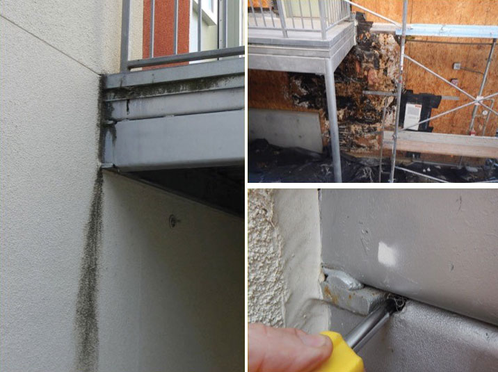
Figure 9. Steel stair landing. Images are actually taken from multiple examples of this landing type.
So if steel isn’t necessarily the solution in and of itself, should the industry stay with wood? Durability of wood is an important consideration for appendages. Perhaps evaluating the project specific conditions that may create challenges to achieving a well performing moisture barrier warrants considering the use of preservative treated members. However, the use of preservative treated lumber also requires consideration of corrosion of fasteners and hardware. As noted above, this is a complicated issue, with no simple solution.
Summary
In summary, the structural engineer should become versed in the issues involved in waterproofing design, for no other reason than as a means for risk reduction. The structural engineer can do the following to improve the current situation:
1) Confirm that the project actually has a building envelope and waterproofing designer.
2) Enhance coordination between the structural and architectural details, particularly at appendages and structural interfaces (stair stringers, guardrail anchorage, ledger attachments, cantilevered members, etc.).
3) Recognize the importance of drainage and slope for the performance of all waterproofing systems.
4) Use more durable materials such as pressure preservative treated lumber and steel but recognize that they have their own design challenges such as corrosion.
5) Know the 4 Ds.
Acknowledgements
Several prominent structural engineers provided steering and technical review. The authors sincerely thank them.▪