
A Critical Comparison of Auger Cast and Prestressed Piles in Areas of Moderate to High Seismicity
Design of auger cast and prestressed concrete pile elements supporting building structures in Seismic Design Categories A through F is covered in Chapter 18 of the 2015 International Building Code (IBC). It is anticipated that subsequent additions of the IBC will no longer contain these provisions and ACI 318 is currently being revised to include provisions for these elements beginning in 2019. The committee in charge of foundation elements (ACI 318F) is already in the process of carefully studying the history of pile foundation detailing provisions and drafting language applicable to both foundation systems. The purpose of this article is to present shortcomings associated with the current prescriptive seismic design philosophy used for both auger cast piles and prestressed piles, to contrast this design approach with that used for other structures, and to do a side-by-side comparison of issues associated with these two commonly used reinforced concrete foundation elements.
Seismic Design Philosophy
Building piles are designed for lateral forces, axial forces, and bending moments that occur at the top of the pile (e.g., fixed head piles) and below grade, and are the result of significantly reduced earthquake forces caused by the inelastic behavior of the lateral force resisting system above the foundation. Regardless of whether an equivalent lateral force, modal, or elastic/inelastic time history analysis is used for the building itself, actions at the top of the piling, as provided by the structural engineer to the geotechnical engineer, are forces that are based on an anticipated elastic response of the piling. In harmony with this elastic design approach, the 2015 IBC has an allowable lateral load limit of fifty percent of the load causing a deflection of one inch at the top of the foundation element or the ground surface. Standard practice is that the geotechnical engineer provides the structural engineer shear and bending moment diagrams for all piles that consider, as a minimum, the following:
- An appropriate subgrade modulus for each soil layer (i.e., p-y springs),
- Elastic response of the pile using an effective stiffness, and
- Liquefied layers modeled using reduced p-y springs (if applicable).
In areas where liquefaction is likely to occur, the geotechnical engineer usually provides a maximum moment for each pile that is the larger of the results obtained including and neglecting liquefaction, respectively. The purpose for this requirement is twofold. First, although it may be expected, liquefaction may not occur and the foundation should be designed for this scenario. Secondly, it is well known that liquefaction does not occur during the onset of seismic motion. Rather, liquefaction may take place well after the maximum soil movements have taken place. Special provisions do apply for Seismic Design Category (SDC) D and higher when the Site Class has been classified as E or F (IBC Section 1810.2.4.1). The pile systems must be designed to resist maximum earthquake induced pile curvatures resulting from the structure above (i.e., pile head loading) and free-field soil movements/soil-structure interaction. Although this sounds cumbersome, standard practice regarding liquefied layers is already addressed in typical geotechnical reports and other concerns, such as neglecting certain soil support conditions (due to settlement at the top of the pile) and accounting for larger soil movements for soft soils, are easily addressed by the geotechnical engineer as part of the design and recommendation process. In lieu of this slightly more detailed analysis, prestressed piles and auger cast piles can be prescriptively detailed as an “assumed to meet measure” via an exception statement contained in IBC Section 1810.2.4.1. It is the author’s opinion that the devil, as always, is in the details. The IBC philosophy of designing for an elastic response of the piling (see above) is discarded when it comes to pile detailing. Although the engineer is required to conservatively determine demands that suggest an elastic response, prescriptive detailing approaches presented elsewhere in Chapter 18 of the 2015 IBC are based on significant inelastic behavior of the pile system. It is as if the engineer is being told, “make sure the pile only moves 0.5 inches at the top but detail it to move 6 inches just in case.” Granted, the previous statement is purposely facetious but it illustrates the point. It is more important to recognize two facts: 1) The IBC approach of designing for an elastic response but detailing pile foundations to handle extreme inelastic behavior is not a surprise, nor unjustified. It is the downfall of prescriptive design. Given uncertainties in the geotechnical assumptions, the IBC committees have always been concerned that even though an elastic response may be expected, pile ductility might still be required. Uncertain how much ductility to require and where it might occur, the committees have continually required seismic ductility levels similar to those used for columns used as special reinforced concrete moment frames. 2) Pile designers must be made aware that the stringent detailing for pile design has never been required in the first place (i.e., performance based design has always been allowed under the current code provisions). Designers are permitted to base the reinforcement required on more advanced pile analysis procedures as used in the design of other structures such as bridges, piers, and wharves, but these approaches have yet to catch on in the building industry. Design procedures for prestressed concrete piling in areas of moderate to high seismicity vary significantly for bridge and building structures. Bridge foundations and substructures are usually detailed such that global earthquake forces are reduced by column, bent, and/or pile energy dissipation via the formation of plastic hinges in these elements. Design procedures for bridge foundations (Caltrans, SCDOT) and those for pier and wharf type structures (MOTEMS) are based on a performance based design procedure that allows the design professional to detail piles based on their anticipated level of inelastic behavior during the design earthquake. More specifically, the design professional provides an appropriate amount of spiral reinforcing to ensure that plastic hinges that develop in the pile are capable of adequate rotation, as required by a pushover or time history analysis.
Comparison of Design Provisions
Neglecting the fact that auger cast piles are not typically permitted by AASHTO (nor local DOT provisions) for support of bridge structures, the previous discussion regarding pile reinforcement detailing and seismic design philosophies is applicable to both auger cast and prestressed piles (i.e., drilled shafts and other cast in place piles are permitted by AASHTO and are somewhat similar to auger cast piles in their final form). However, there are many 2015 IBC provisions regarding the design of auger cast and prestressed piles that suggests that the two systems are being designed for very different analysis, design, detailing, and construction criteria. Some of the most critical points are summarized below: 1) Auger cast pile designers are permitted to reduce confinement steel 50% in Site Classes A through D for SDCs A, B, and C. This reduction is in addition to an already relaxed requirement as compared to prescriptive requirements for prestressed piles. The allowance for less confinement is based on the committee opinion that the soil surrounding the auger cast pile (in response to the form like grout pressure) is firm enough to act in place of the missing transverse steel. A similar provision is not included in the 2015 IBC for prestressed piles (which actually displace soil), even though experimental research performed on prestressed piles has actually justified the reduction when stiff soil is present and the fact that the displaced soil is under increased confining pressure (Budek et al., 1997). It is the author’s opinion that neither foundation type should get this reduction. Recent research, and common sense, show clearly that cyclic loads cause separation between the pile face and the supported soil in the ductile region of the pile (i.e., this confinement is not guaranteed when using prescriptive design). 2) The 2015 IBC does not mandate or recommend specific resistance factors for different pile types. The code does, however, refer to “approved” methods. It should be noted that AASHTO and state specific bridge standards present different resistance factors for each pile type. Specifically, and consistent with an LRFD philosophy, these codes uniformly assign larger resistance factors for prestressed piles as compared to cast in place piles and thereby assigns greater design capacity to the prestressed piles of the same size. An example is provided below. Example Resistance Factors (typical of bridge construction): Driven Pile (with PDA): 0.85 Driven Pile (with Wave Equation): 0.75 Shafts with Single Test (IGM): 0.55 Shafts (other): 0.45 The 2015 IBC recognizes through reference of “approved” methods that the geotechnical reliability of auger cast and prestressed piles are different as a result of both construction and testing considerations (i.e., prestressed piles are tested piles by nature of installation techniques). However, it is the author’s opinion that the language is not strong enough. A survey of geotechnical engineers practicing on the east coast suggests that common practice is to consider the geotechnical capacity of both foundation types as identical for the same size pile when doing building reports, yet to conclude the prestressed piles are substantially stronger when writing bridge reports. A simple additional phrase such as “approved methods including an appropriate consideration of geotechnical resistance factors” eliminates this problem.
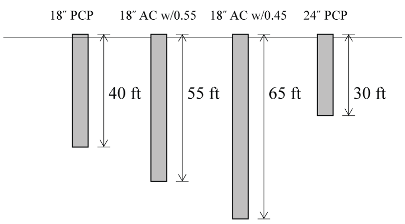
A comparison of typical required foundation sizes for the same demand based on example resistance factors. Note that AC stands for auger cast and PCP stands for prestressed concrete pile.
3) The 2015 IBC does not mandate or recommend specific subsidence demand factors for different pile types. The code does, however, refer to “approved” methods. It is well established in the literature that as a result of higher soil-pile friction stresses, auger cast piles are subjected to significantly higher load effects from soil subsidence than are prestressed piles of the same size. Modification for this effect is not as easy to resolve as item 2 above, but it is the author’s opinion that geotechnical engineers should be made aware of this discrepancy. 4) Placement of longitudinal steel and rebar cages in semifluid grout is one of the biggest issues with auger cast piles. Experience has shown that there is no way to ensure that rebar cages of any reasonable length are set in the grout column in accordance with the construction documents. Durability and bending strength can be severely compromised when the cage is not set with the level of precision specified elsewhere in ACI 318-11 for other types of reinforced concrete members. When the cracking moment is exceeded, a reinforced cage should always be used since the placement of one vertical bar is even more prone to misplacement and its impact on bending strength is negligible. Also, the designer should note that the 2015 IBC does not (but likely should) require that the longitudinal reinforcement that extends to the location of the cracking moment extend one development length beyond this location. This detailing methodology is inconsistent with traditional ACI 318 design approaches for moment resistance in reinforced concrete members. The most critical discrepancy between auger cast and prestressed piles actually ties back to the initial discussion on seismic design and reinforcing requirements. Most notable is the required amount of spiral for both pile types considering Seismic Design Category (SDC) C and SDCs D through F. The amount of spiral required in the 2015 IBC for each pile type is summarized below.
Spiral Requirements for Auger Cast Piles – SDC C
No specific volumetric ratio of spiral is required. However, the minimum permitted spiral diameter is 3/8 inches and the maximum spacing of the transverse steel is specified in Table 1.
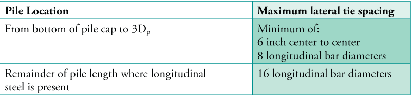
Table 1. Maximum lateral tie and spiral spacing requirements for auger cast piles (SDC C). The term Dp denotes pile diameter.
Spiral Requirements for Auger Cast Piles – SDC D through SDC F
The volumetric spiral ratio ρs = volume of spiral/volume of core (measured out-to-out of spiral) must equal or exceed the following: ρs,min = 0.12 [pmath]{f prime_c}/{f_yh}[/pmath] where fyh is the yield stress of the spiral reinforcement. Maximum spacing of the transverse steel is specified in Table 2.
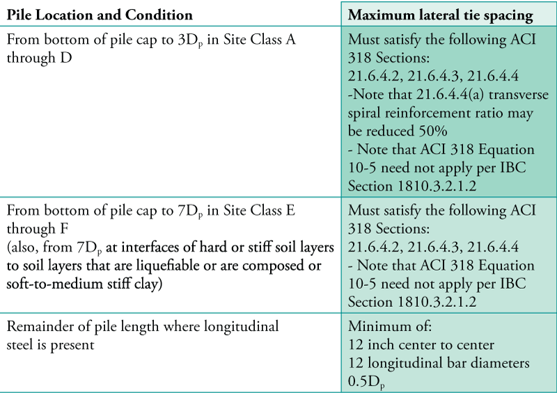
Table 2. Maximum lateral tie and spiral spacing requirements for auger cast piles (SDCs D, E, and F).
Spiral Requirements for Prestressed Piles – SDC C
Sufficient transverse reinforcement must be provided in the upper 20 feet of the pile length such that the spiral reinforcement index exceeds the following: ρs,min = 0.12 [pmath]{f prime_c}/{f_yh}[/pmath] where fyh is the yield stress of the spiral reinforcement not to be taken as larger than 85,000 psi. For the remaining length of the pile, half the minimum transverse reinforcement specified above must be provided.
Spiral Requirements for Prestressed Piles – SDC D through SDC F
In the pile’s ductile region, which includes up to the top 35 feet of the pile length, the spiral reinforcement index must equal or exceed the following: ρs,min = 0.25 [pmath]{f prime_c}/{f_yh}[/pmath]( [pmath]A_g/{A_ch}[/pmath] – 1)(0.5 + 1.4 [pmath]P/{f prime_c A_g}[/pmath] ) ≥ max 0.12 [pmath]{f prime_c}/{f_yh}[/pmath] (0.5 + 1.4 [pmath]P/{f prime_c A_g}[/pmath]) and 0.12 [pmath]{f prime_c}/{f_yh}[/pmath] where Ach is the cross-sectional area of the confined core (measured out-to-out of spiral), Ag is the gross cross-sectional area of the pile, and P is the factored compressive load on the pile using either IBC Equation 16-5 or 16-7 as applicable. Note that the minimum spiral reinforcement index need not be taken as greater than 0.021 (i.e., ρs,min ≤ 0.021).
Comparison of Spiral Requirements
A quick comparison of the spiral requirements presented above manifests that the quantity of spiral required and the length of pile over which this spiral is required is much greater for prestressed piles as compared to auger cast piles. For example, why is the SDC D volumetric ratio required for auger cast spiral equal to that required for prestressed piles in SDC C? Also, why is the expected length of curvature ductility demand so much greater for prestressed piles when no soil structure interaction model comparing the two pile types would suggest this would be the case? The spiral requirements for prestressed piles are based on extensive flexural ductility tests performed on actual piles and conclusions made in the Recommended Practice for Design, Manufacture and Installation of Prestressed Concrete Piling (1993). It is unclear to this author why auger cast piles have such relaxed prescriptive spiral requirements. The Recommended Practice for Design, Manufacture and Installation of Prestressed Concrete Piling (1993) is undergoing major revisions at the time of this writing. However, it is important to note that new research performed for PCI (Fanous et al., 2010) is being used to justify that even more spiral should be used in SDCs C through F. PCI has established required curvature ductility demands of 12 and 18 in areas of moderate and high seismicity, respectively, as target values for design, and will also encourage the designer to use performance based design to justify more accurate quantities when advanced soil structure interaction modeling is included as part of the design process. It is the author’s recommendation that unless performance based design methodologies are used, both pile types have the same length of pile segments detailed for the same prescriptive ductility capacities so that both piles can be assumed to provide the same level of safety in response to the design earthquake.
Acknowledgements
The author wishes to thank the Precast/Prestressed Concrete Institute (PCI) for partially funding this study comparing driven prestressed concrete piles to auger-cast piling. During this last year of study, the questions and input from the committee members of PCI has not only enhanced the knowledge of those that participated but also allowed this author to coalesce a better understanding for how to approach the need for legacy methods and performance-based seismic provisions here in my home state of South Carolina.▪
References
2015 International Building Code, International Code Council, Inc., Washington, D.C. ACI 318-14, Building Code Requirements for Structural Concrete and Commentary, American Concrete Institute. AASHTO LRFD Bridge Design Specifications, Customary U.S. Units, 6th Edition, with 2013 Interim Revisions. Budek, A.M., Benzoni, G. and Priestly, M.J.N., 1997. Experimental Investigation of Ductility of In-Ground Hinges in Solid and Hollow Prestressed Piles, Report No. SSRP-97/17, University of California, San Diego. Caltrans. Seismic Design Criteria, California Department of Transportation, Sacramento, CA Fanous, A., S. Sritharan, M. Suleiman, J. Huang, and K. Arulmoli. Minimum Spiral Reinforcement Requirements and Lateral Displacement Limits for Prestressed Concrete Piles in High Seismic Regions, ISU-ERI-Ames Report ERI-10321, September 2010. MOTEMS. The Marine Oil Terminal Engineering and Maintenance Standards, codified as Chapter 31F (Marine Oil Terminals), Title 24, California Code of Regulations, Part 2, California Building Code. PCI Committee on Prestressed Concrete Piling, “Recommended Practice for Design, Manufacture and Installation of Prestressed Concrete Piling,” PCI Journal, V. 38, No. 2, March-April 1993, pp.64-83. SCDOT. Seismic Design Specifications for Highway Bridges, South Carolina Department of Transportation, Columbia, SC.