
The next edition of ASCE 7 Minimum Design Loads for Buildings and Other Structures, ASCE 7-16 (ASCE, 2016), is expected to be published in September 2016, in time for adoption into the 2018 International Building Code (IBC) (ICC, 2018). For that edition, ASCE 7-10 (ASCE, 2010) has been modified to include a new Section 12.10.3, Alternative Design Provisions for Diaphragms including Chords and Collectors, within Section 12.10, Diaphragm Chords and Collectors. The new section provides for an alternative determination of diaphragm design force level, which is mandatory for precast concrete diaphragms in buildings assigned to SDC C, D, E, or F. The alternative is permitted to be used for other precast concrete diaphragms, cast-in-place concrete diaphragms, and wood sheathed diaphragms on wood framing. Section 12.10.3 does not apply to steel deck diaphragms. ASCE 7-10 has also been modified to add a Section 14.2.4, containing detailed seismic design provisions for precast concrete diaphragms including a connector qualification protocol. Chapter 14 of ASCE 7-10 is currently not adopted by the 2012 or 2015 IBC (ICC, 2012, 2015). Steps directed towards the inclusion of ASCE 7-16 Section 14.2.4 in the 2018 IBC are now being taken.
Both changes originated in the 2015 NEHRP Recommended Provisions for Buildings and Other Structures (FEMA, 2015). This article is devoted to a discussion of ASCE 7-16 Section 12.10.3, Alternative Design Provisions for Diaphragms including Chords and Collectors.
Basis and Overview
The seismic design of structures has long been based on an approximation of the inelastic response of the seismic force-resisting system. The approximation reduces the results of an elastic analysis in consideration of the reserve strength, ductility, and energy dissipation inherent in the vertical elements of the seismic force-resisting system. In 1978, ATC-3 (ATC, 1978) provided design force reduction factors based on consideration of inelastic behavior of the vertical elements of the seismic force-resisting system and the performance of structures in past earthquakes. The primary assumption leading to these factors is that yielding in the vertical elements of the seismic force-resisting system is the primary mechanism for inelastic behavior and energy dissipation. Starting with the 1997 Uniform Building Code (UBC) (ICBO, 1997), the actual forces and displacements that might occur in the vertical elements in a design-level seismic event were recognized with the introduction of a seismic force amplification factors, Ω0, and deflection amplification factor, Cd, respectively. In contrast, the design requirements for the horizontal elements of the lateral force-resisting system (the diaphragms) have been established by empirical considerations related to anticipated behavior of the vertical elements, rather than explicitly considering behavior of the diaphragms. For established diaphragm construction types, this empirical approach has been generally satisfactory. Satisfactory system performance, however, requires that the diaphragms have sufficient strength and ductility to mobilize the inelastic behavior of the vertical elements.
In order to help achieve the intended seismic performance of structures, the designs of horizontal and vertical elements of the seismic force-resisting system need to be made more consistent. Analytical results, as well as experimental results from shake-table tests in Japan, Mexico, and the United States, have shown that diaphragm forces over much of the height of the structure actually experienced in the design-level earthquake may at times be significantly greater than code-level diaphragm design forces, particularly where diaphragm response is near-elastic. Overstrength and ductility of the diaphragm, however, may account for satisfactory diaphragm performance. ASCE 7-16 Section 12.10.3 ties the design of diaphragms to levels of force and deformation capacity that represent actual anticipated behavior.
ASCE 7-16 Section 12.10.3 presents a near-elastic diaphragm force as the statistical sum of first mode effect and higher mode effects (Rodriguez et al., 2002). The first mode effect is reduced by the R-factor of the seismic force-resisting system, but then amplified by the overstrength factor, Ω0, because vertical element overstrength will generate higher first mode forces in the diaphragm. The effect caused by higher mode response is not reduced. In recognition of the deformation capacity and overstrength of the diaphragm, the elastic diaphragm force from the first and higher modes of response is then reduced by a diaphragm force reduction factor, Rs.
With the modification by Rs, the proposed design force level may not be significantly different from the diaphragm design force level of ASCE 7-16 Sections 12.10.1 and 12.10.2 for many practical cases. For some types of diaphragms and for some locations within structures, the proposed diaphragm design forces will change significantly, resulting in noticeable changes to resulting construction. Based on data from testing and analysis, and on building performance observations, it is believed that these changes are warranted.
The alternative design force level of Section 12.10.3 is based on work by Rodriguez, Restrepo, and Carr (Rodriguez et al., 2002), verified by more recent work by Fleischman et al. (Pankow, 2014).
Current Diaphragm Seismic Design Force Level
Current seismic design forces for diaphragms in ASCE 7-10, to be retained in ASCE 7-16, are a function of the design forces acting on the vertical elements and are, therefore, reduced by the R-factor that applies to the vertical elements. Upper- and Lower-bound limits on the forces are added, as shown in Equation 1.
0.2 SDS Ie wpx ≤ Fpx = [pmath]sum{i=x}{n}{F_i}/sum{i=x}{n}{w_i}[/pmath] wpx ≤ 0.4 SDS Ie wpx Equation 1
where
Fpx is the diaphragm design force at Level x.
Fi is the portion of the seismic base shear, V, induced at Level i.
wi is the weight tributary to Level i.
wpx is the weight tributary to the diaphragm at Level x.
SDS is the design spectral response acceleration parameter at short periods.
Ie is the seismic importance factor.
This empirical seismic design force level has generally resulted in satisfactory performance of diaphragms in earthquakes, as evidenced by a lack of observed severe damage. Material-specific factors related to diaphragm over-strength and deformation capacity may account for the adequate performance.
Results using analysis tools not available when the empirical rules were first established, indicate that the level of force required for design of diaphragms in new code-compliant buildings may not ensure development of inelastic mechanisms in the vertical elements of the seismic force-resisting system. This is particularly true where diaphragms have limited ductility and displacement capacity, as dramatically illustrated by the response of several shear wall structures during the Northridge Earthquake.
Alternative Diaphragm Seismic Design Force Level
The alternative diaphragm seismic design force level is for buildings in which response of the vertical elements of the seismic force-resisting system dominates the overall structure behavior. It is not meant for buildings in which the seismic response is dominated by the diaphragms (as can occur in big-box buildings with flexible diaphragms). The latter buildings are treated in FEMA P-1026 (FEMA, 2015a).
Diaphragm Design Force at Any Level
The alternative diaphragm design force is given in Equations 2 and 3.
Fpx = [pmath]C_px/R_s[/pmath] wpx Equation 2
≥ 0.2 SDS Ie wpx Equation 3
where:
Cpx is the diaphragm design acceleration coefficient at Level x.
Rs is the diaphragm design force reduction factor.
Cp0 is the diaphragm design acceleration coefficient at the structure base.
Cpn is the diaphragm design acceleration coefficient at the top of the structure.
Rs is given in Table 1.
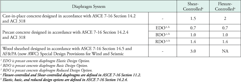
Table 1. Diaphragm Design Force Reduction factor, Rs
The definitions of flexure-controlled and shear-controlled diaphragms in ASCE 7-16 Section 11.2 are as follows:
Flexure-Controlled Diaphragm: Diaphragm with a flexural yielding mechanism, which limits the maximum forces that develop in the diaphragm, and having a design shear strength or factored nominal shear capacity greater than the shear corresponding to the nominal flexural strength.
Shear-Controlled Diaphragm: Diaphragm that does not meet the requirements of a flexure-controlled diaphragm.
The precast concrete diaphragm design options are defined in ASCE 7-16 Section 14.2.4 as follows:
Basic Design Option (BDO): An option where elastic diaphragm response in the design earthquake is targeted.
Elastic Design Option (EDO): An option where elastic diaphragm response in the maximum considered earthquake is targeted.
Reduced Design Option (RDO): An option that permits limited diaphragm yielding in the design earthquake.
Distribution of Diaphragm Design Force along Height
As per Equation 2, the distribution of diaphragm design forces over the height of the structure varies as a function of Cpx. For structures of three or more stories, Cpx varies linearly between Cp0 at the base and Cpi at 80% of structural height, hn, above the base. It then varies linearly between Cpi at 0.8hn to Cpn at hn, as shown on the right hand portion of Figure 1. For one and two stories, Cpx varies between Cp0 and Cpn, as shown in the left had portion of Figure 1.
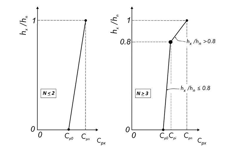
Figure 1. Floor acceleration envelopes for calculating the design acceleration coefficient Cpx in buildings with n ≤ 2 and in buildings with n ≥ 3.
In order to determine Cpx, it is necessary to first determine Cp0, Cpi, and Cpn.
Cp0 = 0.4 SDS Ie wpx Equation 4
Cpi is the greater of values given by:
Cpi = Cp0 Equation 5
Cpi = 0.9Γm1 Ω0 Cs Equation 6
where:
Γm1 is first mode contribution factor
Γm1 = 1 + 0.5zs (1 – [pmath]1/N[/pmath]) Equation 7
zs = modal contribution coefficient modifier dependent on seismic force-resisting system, as given in Table 2.
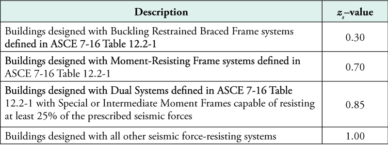
Table 2. Modal Contribution Coefficient Modifier, zs.
Cpn = [pmath]sqrt{(Gamma_m1 Omega_0 C_s )^2 + ( Gamma_m2 C_s2 )^2}[/pmath] ≥ Cpi Equation 8
where:
Γm2 is higher mode contribution factor
Γm2 = 0.9 zs (1 – [pmath]1/N[/pmath])2 Equation 9
Cs2 is higher mode seismic response coefficient. Cs2 is the smallest of values given by
Cs2 = (0.15N + 0.25) Ie SDS Equation 10
Cs2 = Ie SDS Equation 11
Cs2 = [pmath]{I_e S_D1}/{0.03 (N-1)}[/pmath] For N ≥ 2 Equation 12
Cs2 = 0 For N = 1 Equation 13
Validation
To validate the alternative seismic design force level, coefficients Cpx were calculated for various buildings tested on a shake table. Figures 2 and 3 plot the floor acceleration envelopes and the floor accelerations predicted from Equations 2 and 3 with Rs = 1 for two buildings built at full-scale and tested on a shake table (Panagiotou et al., 2011; Chen et al., 2013). Cp0 is defined as the diaphragm design acceleration coefficient at the structure base, and Cpx is defined as the diaphragm design acceleration coefficient at Level x. The vertical distribution of measured floor accelerations is reasonably predicted by Equations 2 and 3.
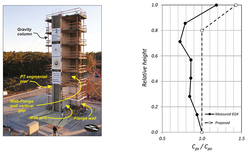
Figure 2. Comparison of measured floor accelerations and accelerations predicted by Equations 2 and 3 for a 7-story bearing wall building (Panagiotou et al., 2011).
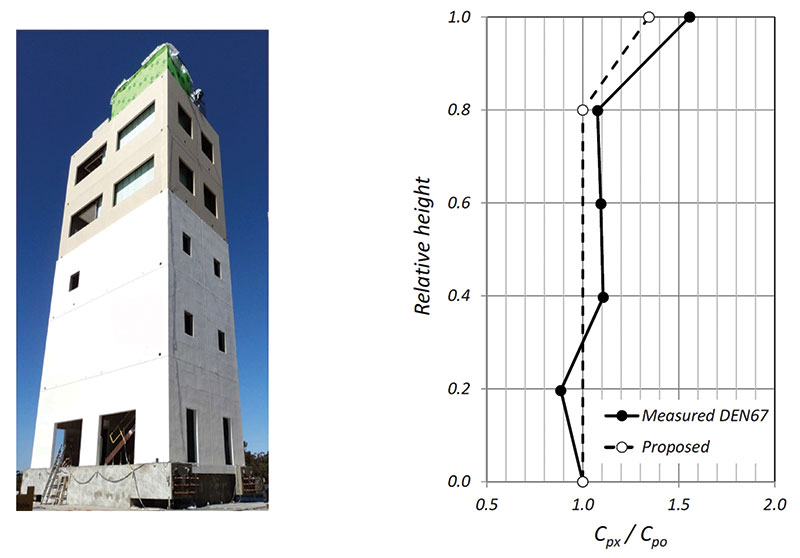
Figure 3. Comparison of measured floor accelerations and accelerations predicted by Equations 2 and 3 for a 5-story special MRF building (Chen et al., 2013).
Research work by Choi et al. (2008) concluded that buckling-restrained braced frames are very effective in limiting floor accelerations in buildings arising from higher-mode effects. This finding is reflected in the provisions of ASE 7-16 Section 12.10.3, where the mode shape factor zs has been made the smallest for buckling-restrained braced frame systems. Figure 4 compares vertical distributions of average floor accelerations obtained from the nonlinear time-history analysis of four buildings (two steel buckling-restrained braced frame systems and two steel special moment frame systems) when subjected to an ensemble of spectrum-compatible earthquakes with floor accelerations computed from Equations 2 and 3, normalized to accelerations at the structure base. The proposed design equations predict the vertical distribution of accelerations in both the uppermost part of the building and in the lowest levels reasonably well.
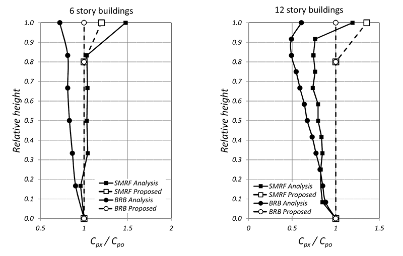
Figure 4. Comparison of measured floor accelerations with accelerations predicted by Equations 2 and 3 for steel BRBF and special MRF buildings (adapted from Choi et al., 2008).
Comparisons of Design Force Levels
Comparisons of diaphragm seismic design force levels along the heights of a number of buildings of various materials and assigned to various SDCs have been made. A few representative cases are shown below. For more comparisons, see FEMA P-1051 (FEMA, 2016).
4-Story Perimeter Wall Precast Concrete Parking Structure in Knoxville, TN
The structure for this example is a 4-story perimeter shear wall precast concrete parking garage. The lateral force-resisting system (LFRS) in the transverse direction is composed of four perimeter precast walls, two at each end of the structure. The LFRS in the longitudinal direction consists of interior lite walls flanking the central ramp. The SDC is C.
The comparison of diaphragm design force levels for the structure by ASCE 7-16 Sections 12.10.1 and 12.10.2 (marked ASCE 7), by ASCE 7-16 Section 12.10.3 (marked ASCE 7 Alt.), and by the 2015 NEHRP Provisions (labeled NEHRP), are illustrated in Figure 5. EDO, BDO, and RDO in the figure stand for Elastic, Basic, and Reduced Design Options, respectively. A few changes were made to alternative design force level provisions of the 2015 NEHRP Provisions before they were adopted into ASCE 7-16. Those differences are not important for the purposes of this brief article.
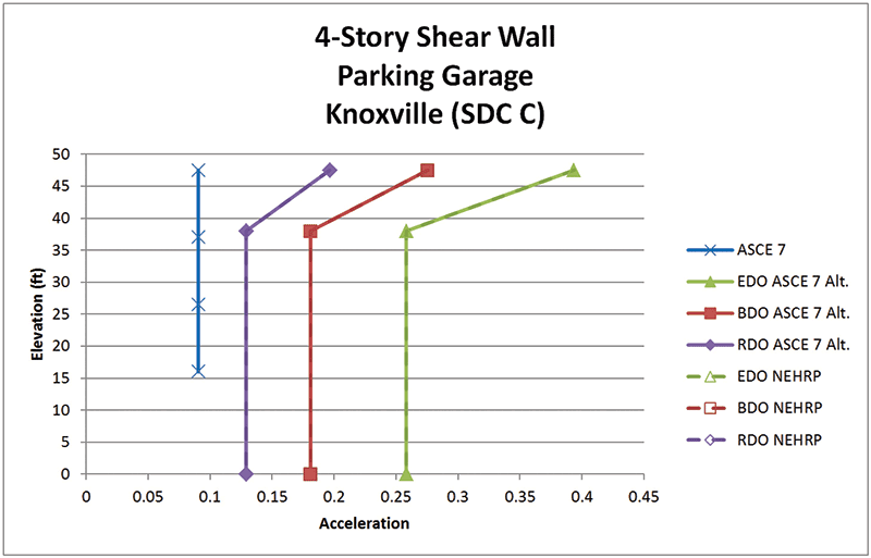
Figure 5. Design force level comparisons for precast concrete parking structure. (All references to ASCE 7 and NEHRP are to ASCE 7-16 and the 2015 NEHRP Provisions, respectively) [Reproduced with permission from FEMA from the upcoming FEMA P-1051].
Steel-Framed Office Structure in Seattle, WA
The structure for this example is a 12-story buckling-restrained braced frame office building in Seattle, WA. The SDC is D.
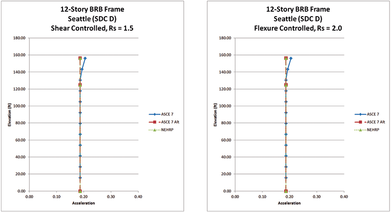
Figure 6. Design force level comparisons for 12-story steel-framed office structure (References to ASCE 7 and NEHRP are to ASCE 7-16 and the 2015 NEHRP Provisions, respectively) [Reproduced with permission from FEMA from the upcoming FEMA P-1051].
Cast-in-Place Concrete Shear Wall Residential Structure in Northern California
The structure for this example is a 15-story reinforced concrete special shear wall residential structure in northern California. The SDC is D.
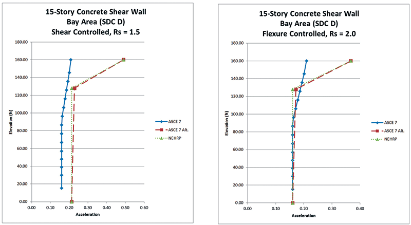
Figure 7. Design force level comparisons for 15-story concrete shear wall residential structure (References to ASCE 7 and NEHRP are to ASCE 7-16 and the 2015 NEHRP Provisions, respectively)[Reproduced with permission from FEMA from the upcoming FEMA P-1051].
Conclusion
The alternative diaphragm seismic design force level of ASCE 7-16, mandated for precast concrete diaphragms in buildings assigned to SDC C and above and permitted for other precast concrete diaphragms, cast-in-place concrete diaphragms, and wood sheathed diaphragms on wood framing, departs from the current empirical approach and brings the design forces closer to reality as indicated by observations, test results, and analytical results. The reader is encouraged to consult the 2015 NEHRP Provisions (FEMA, 2015) and commentary for more detailed discussion of the alternative procedure and development of the diaphragm force reduction factor Rs.▪
Acknowledgments
Kelly Cobeen, Jose Restrepo, and Mario Rodriguez contributed significantly to the research, understanding and codification of the material presented in this article. Their efforts, along with those of the other members of Issue Team 6 of the Provisions Update Committee of the Building Seismic Safety Council, originators of the alternative diaphragm design force level, are gratefully acknowledged.
References
American Society of Civil Engineers (ASCE). (2010, 2016). Minimum Design Loads for Buildigs and Other Structures. ASCE 7. Reston, VA.
Applied Technology Council (ATC). (1978). Tentative Provisions for the Development of Seismic Regulations for Buildings. ATC-3-06, Redwood City, CA.
Chen, M., Pantoli E., Astroza R., Ebrahimian H., Mintz S., Wang X., Hutchinson T., Conte J., Restrepo J., Meacham B., Kim J., and Park H. (2013). Full-Scale Structural and Nonstructural Building System Performance during Earthquakes and Post-Earthquake Fire: Specimen Design, Construction and Test Protocol. Structural Systems Research Project Report Series. University of California San Diego, San Diego, CA.
Choi, H., Erochko, J., Christopoulos, C and Tremblay, R. (2008). Comparison of the Seismic Response of Steel Buildings Incorporating Self‐Centering Energy‐Dissipative Braces, Buckling Restrained Braces and Moment‐Resisting Frames. Research Report 05-2008, University of Toronto, Canada.
Federal Emergency Management Agency (FEMA). (2015). NEHRP Recommended Provisions for Seismic Regulations for New Buildings and Other Structures. Prepared by the Building Seismic Safety Council for the Federal Emergency Management Agency, Washington, DC.
Federal Emergency Management Agency (FEMA). (2015a). Seismic Design of Rigid Wall-Flexible Diaphragm Buildings. Prepared by the Building Seismic Safety Council for the Federal Emergency Management Agency, Washington, DC.
Federal Emergency Management Agency (FEMA). (2016). 2015 NERP Recommended Seismic Provisions: Design Examples. Prepared by the Building Seismic Safety Council for the Federal Emergency Management Agency, Washington, DC.
International Conference of Bulldog Officials (ICBO). (1997). Uniform Building Code. Whittier, CA.
International Code Council (ICC). (2012, 2015, 2018). International Building Code. Country Club Hills, IL.
Panagiotou, M, Restrepo, J, and Conte J.P. (2011). “Shake-Table Test of a Full-Scale 7-Story Building Slice. Phase I: Rectangular Wall”, ASCE J. Struct. Engr., 137(6), 691-704.
Pankow Foundation. (2014). Seismic Design Methodology Document for Precast Concrete.Vancouver, Washington.
Rodriguez, M, Restrepo, J. I. and Carr, A. J. (2002). “Earthquake Induced Floor Horizontal Accelerations in Buildings”, Earthquake Engineering – Structural Dynamics, Vol. 31, pp.693-718.