
Steel Fiber Reinforced Concrete Solves Seismic Design Challenges
Bellevue, Washington continues to blossom into a vibrant, world class city. The Lincoln Square Expansion (LSE) broke ground in downtown Bellevue in June 2014 and, when complete in 2017, will add two 450-foot towers, a four level retail podium, and six levels of subterranean parking to Bellevue’s urban core. LSE is an excellent example of how innovative structural design can respond to high seismic requirements and still meet demanding architectural programs.
The 41-story hotel/residential tower will feature a W Hotel and upscale apartments. The 31-story office tower will feature Class-A office space with unparalleled views. Both towers integrate with a podium structure with retail shops and restaurants. The subterranean parking will include 2,200 new parking spaces and connect to adjacent existing underground parking via tunnels.
The hotel/residential tower is cast-in-place concrete with a mix of one-way and two-way post-tensioned slabs, with the office tower and retail podium framed in structural steel. Concrete shear walls resist seismic loads for both towers and the retail podium. The subterranean parking structure utilizes one-way post-tensioned slabs with wide-shallow beams to create large open space and user-friendly parking.
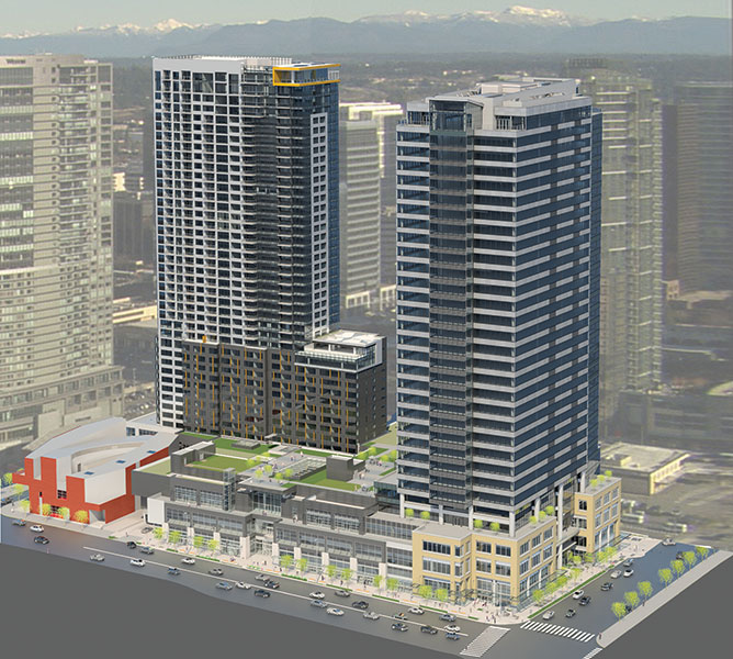
Lincoln Square Expansion (LSE) in Bellevue, WA.
Performance-Based Design
Performance-Based Design (PBD) was key to the structural design of LSE. Essentially, PBD is a methodology for creating acceptable alternates to prescriptive building code requirements, contingent upon demonstrating that the proposed design meets code required seismic performance levels. This is generally accomplished through rigorous non-linear analysis and by checking the stiffness, ductility, and strength of critical elements.
Since LSE consists of two towers and a common podium, careful attention was given to the seismic interaction between these structures. A combined nonlinear model consisting of both towers, the retail podium, and below grade parking was created. The stiffness assumptions for backstay effects between slabs and basement walls were important considerations, since they determined the effective fixity at the base of the towers. Two different sets of assumptions were made for these elements in the nonlinear analysis in order to effectively evaluate an upper and lower bound solution.
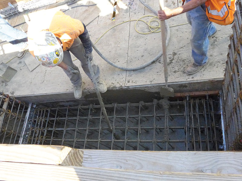
Steel fiber reinforced concrete shear wall coupling beam under construction.
Steel Fiber Reinforced Concrete
Reinforcing congestion has long been the bane of concrete construction in high seismic regions. Some of the most difficult and congested reinforcing is often in shear wall coupling beams. Traditionally, diagonal bars are used to reinforce these coupling beams, combined with tightly spaced stirrups and ties. This creates significant constructability problems since the diagonal bars clash with adjacent shear wall reinforcing.
For the LSE seismic system, PBD provided a means to implement steel fiber reinforced concrete (SFRC) in 341 of 392 total coupling beams. This is significant, since the use of SFRC for seismic design has heretofore been limited. The only prior use of SFRC in seismic coupling beams was in a 24-story tower in Seattle, for which CKC was also the structural engineer.
Modeling of key elements is critical to reliably predicting seismic behavior. The SFRC coupling beams in LSE were of particular importance. Both the initial stiffness and cyclic degradation used in the model were carefully calibrated against the hysteresis loops derived from dynamic lab testing. This hysteretic behavior was then used in the non-linear analytical models.
Dramix© steel fibers manufactured by Bekaert, with a fiber dosage of 200 lb/yd3 (120 kg/m3) of concrete, were used in LSE. The fibers are 0.015-inch (0.38mm) diameter by 1.18-inch (30mm) cold-drawn steel wire with hooked ends for anchorage. Fibers were delivered to the producer in subsets of thirty. The subsets were bonded with water-soluble glue that dissolved when mixed into the concrete, allowing the fibers to separate and disperse throughout the mix. After workability was confirmed at the site, a bucket was used to place coupling beam concrete. A piece of “Stayform” at each end of the coupling beam restrained the SFRC from flowing into the adjacent core walls, which were pumped with high-strength concrete.
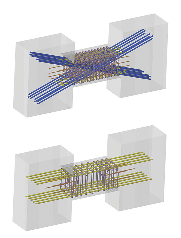
Diagonally reinforced concrete coupling beam (top) and SFRC coupling beam (bottom).
The study of SFRC started at the University of Michigan, with financial support from the National Science Foundation. Further research was funded by the National Science Foundation Network for Earthquake Engineering Simulation, and Bekaert, a Belgium based global supplier of steel fibers. The studies concluded that SFRC coupling beams without diagonal bars achieve similar or better performance, compared to prescriptively designed beams. With SFRC, the stiffness, strength and ductility of coupling beams is maintained, even though a significant quantity of reinforcing steel – including the diagonal bars – is eliminated. Use of SFRC in coupling beams can result in up to a 40 percent reduction in reinforcing and 30 percent net cost savings, compared to traditional coupling beam construction.
SFRC provides the structural engineering profession with a valuable tool for improving the constructability of reinforced concrete buildings in high seismic regions. The use of SFRC in LSE resulted in a coupling beam design that eased reinforcing congestion, facilitated faster construction, and reduced rebar tonnage.
Additional SFRC research is currently underway at the University of Wisconsin, funded by the Charles Pankow Foundation. The results of this testing are expected to broaden the range of fiber types, dosage rates, and aspect ratios available for use by designers of concrete buildings in high seismic regions.
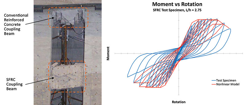
Analytical model calibration with physical testing.
Foundations
Other aspects of LSE are also noteworthy. For example, the hotel/residential tower’s mat foundation, which was completed in February 2015 following the office tower’s mat pour a few weeks earlier, included 13,690 cubic yards of concrete. Both foundation mats utilized 80 ksi ASTM A615 reinforcing. A self-consolidating concrete mix was specified for the bottom 18 inches of the mats to ensure proper consolidation around heavy concentrations of rebar. The remainder was poured with a mix that was designed to minimize heat of hydration and temperature differential from the center to surface of the concrete, which was held to approximately 40 degrees F.
Subterranean Parking
A system of one-way concrete slabs and wide-shallow beams was used in the subterranean parking structure to modulate with tower columns above, creating column-free 50-foot spans throughout. The use of PT in both the beams and slabs lowered the floor-to-floor heights, resulting in reduced excavation and shoring depth. The garage layout partially carries through to the structures above, creating column-free space of 40 by 50 feet in the office tower. The hotel/residential tower was framed with a two-way flat plate system with spans of 25 to 34 feet. Parking columns and columns in the lower levels of the hotel/residential Tower utilized 14,000 psi concrete, specified with a test age of 90 days.
Structural/mechanical integration to increase floor-to-ceiling height.
Office Tower
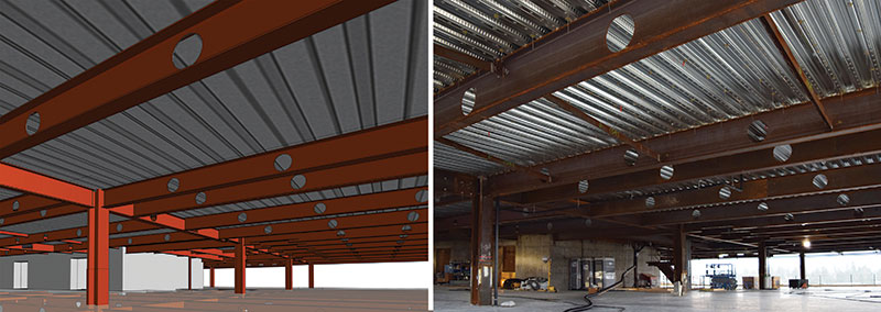
In the office tower, high-strength ASTM A913 Grade 65 structural steel was specified for the columns. This eliminated the need for custom fabricated shapes at the lowest levels where load demands exceeded the capacity of standard Grade 50 column shapes.
Mechanical, electrical, and plumbing (MEP) in the office tower was integrated with the structural steel framing. Penetrations in the steel framing allowed the mechanical systems to feed through the floor framing, which increased the floor-to-ceiling height and allowed for an additional leasable floor in the tower.
The office core was constructed of high-strength concrete, utilizing a high-production climbing form and scaffold system. Prior to starting structural steel erection, the core construction was advanced well ahead to allow simultaneous topping out of both the core and structural steel frame.
Hotel/Residential Tower
The combination of two-way PT slabs along with HSS columns, introduced to control deflections, allowed 14-foot cantilevers on both the north and south ends of the hotel with 8-inch thick PT slabs. The slabs were designed to allow stripping of formwork prior to installation of the HSS columns. For the residential levels above, which are set back approximately 60 feet, the slabs were designed with similar long spans and cantilevers.
Three foot cantilevered outrigger beams were used to lengthen PT slab spans and preclude the need for additional columns in the hotel/residential levels. Sloped columns were used to eliminate transfer beams as the building transitions from the garage to the hotel levels. Together, these elements eliminated all primary column transfers. Additionally, a transition of large shear wall openings in garage levels to smaller openings in the hotel/residential corridors was implemented to maximize coupling of the tower shear walls while still accommodating wide drive aisle openings in the garage.
To eliminate the need for concrete puddling at high strength columns, column concrete was poured continuous through the slabs. “Stayform” was first wrapped around the column reinforcing cage for the depth of the slab to restrain slab concrete from flowing into the column during the slab pour. Column concrete was then placed through the core during the column pour above, providing the required through-slab continuity. Added rebar through the slab/column joints supplements the slab load transfer through shear-friction.
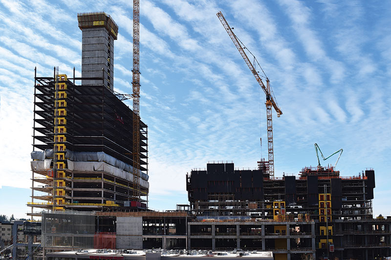
LSE under construction: steel office tower (left) and CIP concrete hotel/residential tower (right). Both towers will be 450 feet high.
Conclusion
The Lincoln Square Expansion in Bellevue, Washington is as an excellent example of how innovative structural design can add value to a multi-use project. LSE both enhances the Bellevue urban landscape and advances the structural engineering profession. Through careful coordination among all parties, CKC’s unique solutions to the design challenges resulted in an efficient structural system, and use of SFRC created a new approach to high-rise building design and construction in high seismic regions.▪
Project Team
Owner/Developer: Kemper Development Company
Structural Engineer: Cary Kopczynski & Company
Architects: HKS Architects / Sclater Architects
Contractor: GLY Construction
Geotechnical Engineer: Hart Crowser