
Frida Restaurant in Torrance, California
One of the most satisfying aspects of being a structural engineer is to see your project constructed. Even more satisfying is knowing you contributed to making something unique, creative, and aesthetically pleasing to society. Inspiration and gratification are rare in any professional endeavor, and the author is pleased to be part of the team that has made this project a reality. The Frida Restaurant definitely brings home that feeling of accomplishment, as the Structural Engineer (SE) staff have worked tirelessly with the Architect, Tag Front Design, to meet the design challenges. As this article is written in November 2015, the contractor is completing the final phase of this restaurant for its Grand Opening by December 15, 2015, and by time of publication the restaurant will be serving customers at the Fashion Mall Plaza in Torrance, California.
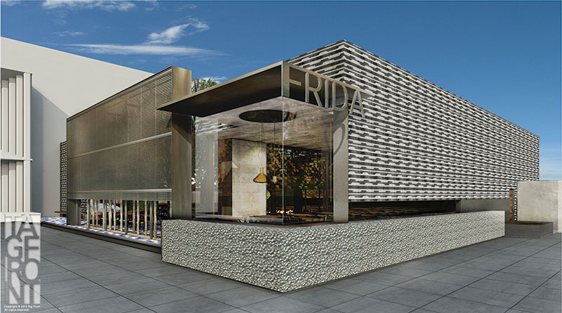
Figure 1. Architectural rendering of front corner elevation of Frida Restaurant.
Why is everyone so excited and proud of this retail project? Several reasons come to mind, but one striking feature of this architectural-engineered design is the roof structure. It is designed to “slide open and closed” similar to a convertible rooftop on a car. Figures 1 through 5 provide illustrations on the creative design concept from the Architect. The roof has perimeter skylights that allow natural light to illuminate the interior areas to create a warm spatial effect, which enhances the dining experience. Perimeter skylights that run the entire length of the roof diaphragm (on both sides) create diaphragm shear transfer issues, which posed structural engineering design challenges. The client wanted an interior space that was “free of columns” and had full opening on all sides, with glass and other architectural features. This eliminated the possible use of a standard shear wall system. An interior bar design is “suspended” from the ceiling with no visible support from the floor (Figure 2). Tag Front designed an open floor plan that is free of visible column supports, but follows no standard grid. Specifically, the floor plan does not follow a standard rectilinear grid system with columns at even spacing. The support system is irregular, and with certain columns taking loading with eccentricity/torsional components to the lateral beams.
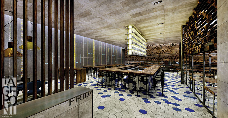
Figure 2. Interior rendering showing the hanging bar design.
Structural Design Solutions
The selection for the lateral force resisting system (LFRS) was steel moment frames with hollow structural steel tube (HSS) columns and tube beams in both directions, connected with ordinary moment frame connections. The HSS columns provided equal moment capacity along both axes, which allowed the design to be balanced efficiently, due to the irregular grid layout. Certain column locations are positioned with eccentric loading from the roof support and/or beam locations, which required extra design effort to make them work. Foundation design utilized spread footings with base moment connections through a pedestal design interconnected with grade beams. Seismic considerations were important, as the site is classified Seismic Design Category “D”. Fortunately, no liquefaction or unusual soil conditions were present. The sliding roof design created additional dead load demand on the structure, which resulted in 16-inch square HSS sections that carry beam spans of up to 20 feet, in order to meet the Architect/Owner criteria of an open floor plan. The additional dead load also resulted in large footings and grade beams because the base moments were high, due to the large loads (when compared to typical single story retail buildings) and long spans of the supporting beams. Lateral drift was critical in the stiffness design of the LFRS to reduce any possible impact to the adjacent mall structure.
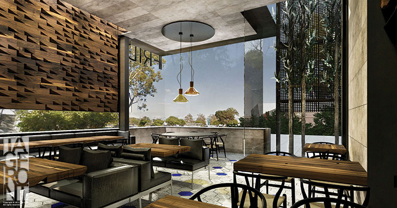
Figure 3. Interior views showing full glass openings with no shear walls.
On the interior, the open floor design is further enhanced by the unique bar design, which is suspended from the ceiling. This consists of structural tubes welded together and “hangs” from a ceiling beam with no support from the foundation. A lateral analysis of the Bar support structure had to prove that the drift did not exceed certain limits so as to endanger the occupants from flying bottles. Similar to the bar, the fire place is designed within a fully-suspended wall with no direct support from the foundation. A steel support beam with a specially fabricated plate cross section was designed to serve this purpose.
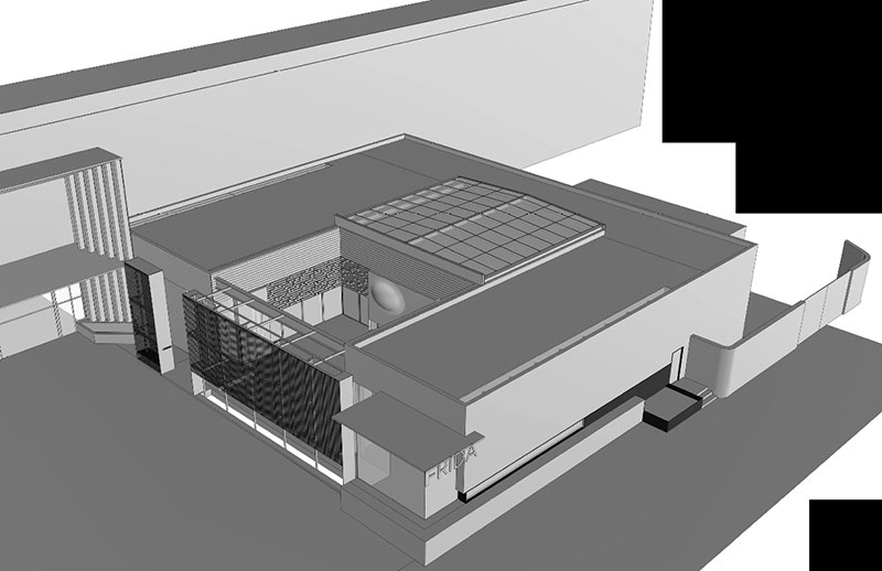
Figure 4. 3D isometric showing sliding roof over garden area.
Retractable Roof Design
This project’s most unique feature is the retractable/sliding roof design, which allows the owner to cover the patio seating area, depending on the weather conditions. The sliding roof is elevated approximately four feet above the rest of the roof plane, which creates some challenges for diaphragm shear transfer and produces torsional bending moments on the supporting beams. The roof structure is supported on two rail beams (i.e., two structural tubes) on both sides, which then transfer the load to vertical tube columns resting on the roof diaphragm beams. Seismic loads do not govern, but the wind loads are substantially higher than the dead loads. The analysis encompassed the use of torsional load transfer with vertical tubes to support the sliding roof through an elevated steel moment frame on top of the building moment frame system. Certainly this is one of the most unique designs the author has worked on in recent years.
Because of timing issues and tight schedules, the sliding roof has to be installed after the restaurant’s opening date in December 2015 and will be completed in the first quarter of 2016.
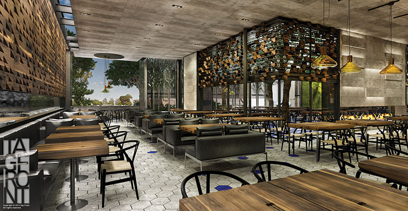
Figure 5. Interior rendering with open space and no column interference.
Collaboration with the Architect, Owner, and Contractor
Tight time frames, short turnarounds, and a critical schedule all characterize the stress level on this project. Structural engineering design is never done in a vacuum, and the SE team collaborated very closely with Tag Front Design and the Contractor to work out the details. During construction there are always change orders, RFIs, and design-construction issues that must be addressed promptly, sometimes leading to heated “discussions”, but at the end of the day the problems must be solved. The author must admit, even after 33 years in the profession, we are always perpetual students of structural engineering. Every project brings new lessons that hopefully make us sharper engineers for the next project. The Frida project definitely taught new solutions to old problems and reemphasized the team relationship with the Owner, Architect, and Contractor. Perhaps the most important contribution that SEs can make to this working relationship is to be available and open to new ideas. Often, our initial reaction when we see the Architect’s concept is to rethink our proposal! However, a project like this is too delicious of a challenge. Be grateful for the experience. The author discovered that collaboration is not just about being a good engineer, but being open to other people’s ideas and suggestions.▪
All photos courtesy of Tag Front Design.
Project Team
Structural Engineer: Khatri International Inc., Pasadena, CA
Owner: Frida Restaurant, Beverly Hills, CA
Architect: Tag Front Design, West Hollywood, CA
Contractor: Ck2d Construction
Roof Manufacturer: Rollamatic Roofs, Inc.
Roof Structural Design: Ficcadenti, Waggoner, & Castle