
Supporting world’s largest LED billboard installation at the crossroads of the world required quick coordination and immediate solutions to conflicts.
The iconic Marriott Marquis hotel, located at the center of Times Square, was recently renovated to display the world’s largest high-definition LED billboard (Figure 1). At five stories tall, this gigantic screen spans the entire width of the building (a full city block, from West 45th Street to West 46th Street on Broadway), wrapping partway around its sides. The renovation also included converting the two underground parking levels and first two above grade-levels to prime double-height retail spaces, the remodeling of back-of-theater rooms, and the creation of new rooftop space offering coveted views of the New Year’s Eve ball dropping.

Figure 1. Marriott Marquis building featuring the world’s largest high definition LED sign.
Project Background
In 1985, as part of the revitalization of Times Square, the Marriott Marquis Hotel, designed by the Architect John Portman, opened. The 574-foot-tall hotel is one of the largest in Manhattan, with 49 floors, 1,946 rooms, a 1,500-seat theater, more than 100,000 square feet of event space, and a revolving roof top restaurant.
The structural engineer, Weidlinger Associates, Inc. (now Thornton Tomasetti), used structural steel framing composed of built-up columns, rolled wide flange columns, and rolled wide flange beams supporting the metal-deck with concrete topping floor system. The hotel features a large atrium with 12 elevators around a concrete core. Standard steel trusses were used at selected locations. Steel Vierendeel trusses were used throughout the building to allow for desirable long spans without having open-rooms interrupted with cross-members.
Since the time the Marriot Marquis opened, Times Square has blossomed into one of the most visited tourist attractions in the world, becoming a commercial center filled with signage, theaters, and stores.
Vornado Realty Trust, which owns multiple retail properties throughout New York City, signed a lease to redevelop the retail space at the Marriott Marquis and install the largest, most technologically advanced LED sign in order to display advertisements in the heart of Times Square. They hired H3 Hardy Collaboration Architecture as the architect; Weidlinger Associates as the structural engineer; and Turner for construction management.
LED Sign Support
To support the 25,740-square-foot LED sign load at the perimeter of the building, the structural engineer had to provide connection points for the various existing conditions around the building, and assess and reinforce the existing steel-framed structure for the new additional load of the LED screen and its back-up structure.
The original building façade consisted of precast panels attached to the perimeter steel beams. Some openings through the panels had already been created to support light signage around the building. Since each of these openings are costly, connection points to the existing framing were minimized and, where possible, connections from previous signage and existing openings in the precast façade were used.
On the north and south faces of the LED sign, corresponding to the 45th and 46th Street facades, the building columns are set back about 8 feet from the façade and cantilever beams extend from these columns to support the existing façade. The support of the new screen was created by extending the cantilever beams. In the instances when the cantilever beams were found not to have the additional capacity required to support the new loading, the beams were reinforced using top and bottom steel plates.
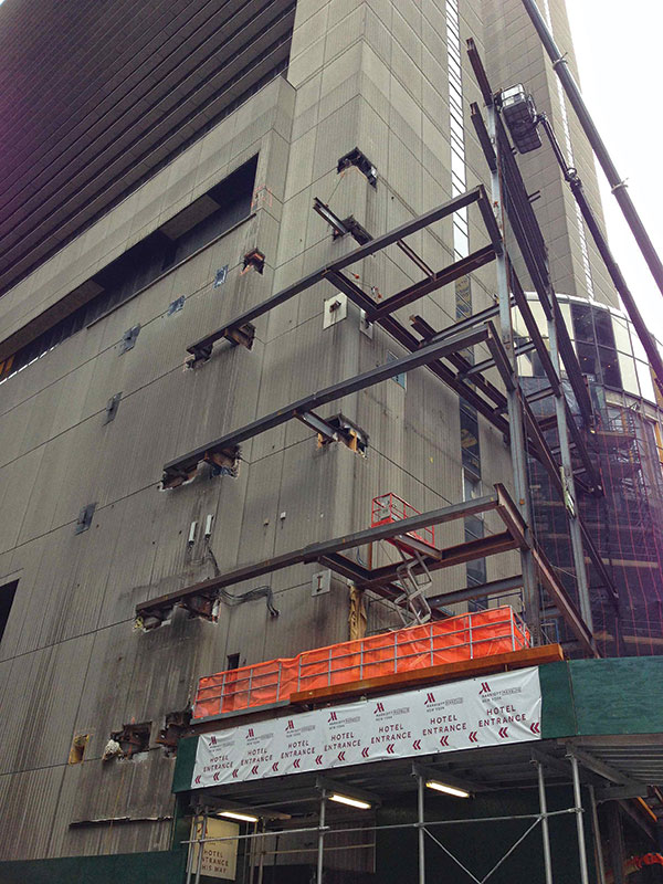
Figure 2. Broadway framing.
The LED screen is five stories tall and is located between levels 3 and 8. The supporting framing for the sign along Broadway was divided into three sections (Figure 2). On the north and south sections, the existing façade was set-back from the property line; at these two areas, the hotel requested open-terraces overlooking Times Square to be constructed on the 8th floor. On the south side, moment frames were constructed along the property line that provided support to both the LED sign and the south terrace. On the north side, a combination of new framing along the property line and framing cantilevering out of existing columns was used. For economy, existing connections and precast openings were also used on the north and south sides of the Broadway facade. In the middle section, above level 6, the existing façade protruded and had to be demolished to install and support the LED sign. The framing in the middle portion of the Broadway façade consisted of hangers suspended from the floors above, and did not have the capacity to support the new load; therefore, the existing structure in this area could not be used. To accommodate the absence of connection points on this portion of the façade and satisfy the stringent limitations on the deflections of members supporting the LED screen, a vierendeel truss was used (Figure 3). The truss spans 57 feet horizontally and has vertical supports only at the existing columns at level 3. It is connected horizontally at only a few discrete points within its 75-foot height to reduce displacement produced by wind loads. The vierendeel truss was selected as the most efficient solution to span the distances between the supports, creating a structure that was robust for both the vertical load and the wind load.
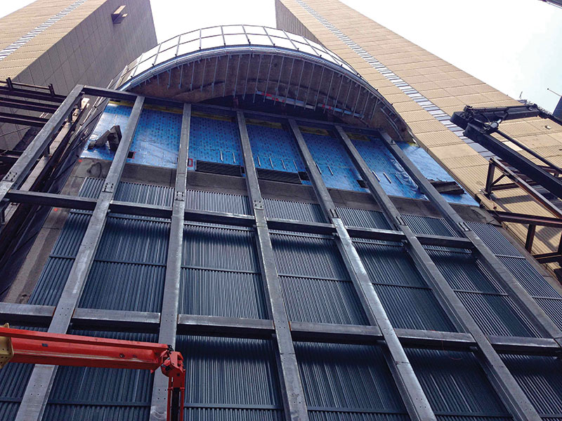
Figure 3. Vierendeel truss.
The LED screen consists of approximately 6- by 8-foot interlocking panels that connect to a secondary or back-up structure connected to the supporting structure described previously. The supporting structure had to be designed for the deflection limits required to accommodate the LED screen; however, it was also very important in the design to control the relative deflections at different support points within the width and height of the screen to avoid having issues during and after the installation of the screen panels. For this reason, sandbags with the same weight as the LED screens were stacked on the back-up structure of the LED sign, allowing for adjustments to be made before the installation of the LED screen and resulting in a successful procedure (Figure 4).
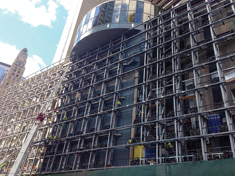
Figure 4. Installation of LED sign.
Interior Work
Achieving the developer’s intent to create ample top-quality retail spaces required the conversion of both underground parking levels and the first two above-ground levels into double-height spaces. To accomplish this, the cellar level and second floor were demolished, making the foundation wall and columns supporting the 44-story tower span twice their original design height (Figure 5). Both the columns and the foundation walls had to be reinforced; the column reinforcing consisted of plates welded to the column flanges, while the additional demand on the foundation wall was resolved by building a steel frame adjacent to the wall. This provided a mid-span support for the wall to bear on the dry-packed horizontal steel members of the frame.
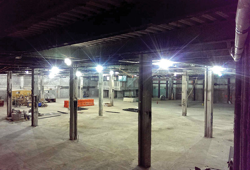
Figure 5. New double story space with reinforced columns.
An important aspect of this work was to devise a sequencing scheme for the reinforcement of the columns and foundation wall that allowed for the demolition of the floor level and also ensured the safety of the structure at all stages. Different types of reinforcing options were evaluated. The main two factors that determined the column reinforcing used were that plating would cause minimum space intrusion and guarantee the stability of structure at all construction stages. The existing columns had the strong-axis capacity to span the two levels, however the weak-axis capacity was insufficient; therefore, the demolition and reinforcing scheme chosen consisted of initially demolishing only the deck and beams bracing the column on its strong axis, then providing the flange plate reinforcing. Once the reinforcement was installed, the increased column section would have sufficient axial capacity in the weak axis to allow for proceeding to demolish the beams that were bracing the columns on the weak axis.
That reinforcing scheme was typical at the two basement levels. Some of the columns on the first two levels above grade also had to be reinforced to allow for double height spaces. These columns were very critical to the structure as they were part of both a vierendeel truss lateral system for the building in one direction and a bracing system used for gravity in the other direction. The moment connected beam of the Vierendeel needed to be removed to allow for an open space. Since these columns were critical to the building, plating sequencing needed special care. Plates on each side of the beam were temporarily installed on the column to provide the required axial capacity. After the beam removal, a plate centered on the column flange was installed that would not protrude as much from the column as the temporary side plates (Figure 6).
Figure 6. Column reinforcing.
The structural interior work also included the floor demolition and design of new beams and reinforcing of existing beams to support stairs, as well as framing evaluation for infill loading at multiple locations in the building. The engineer also devised reinforcement solutions to meet head-height requirements, reducing the depth of a number of beams by as much as 1 foot.
Additional Challenges
Fortunately, the original architectural and structural drawings were available, which helped the design process significantly. However, as in all renovation projects, some conditions in the field are different or not exactly as shown on the existing drawings. In some cases, electrical or architectural equipment was found to impede the construction of structural members as intended in the design phase, and changes to the design had to be made on multiple occasions to accommodate the existing conditions. Conditions found in the field made the work more cumbersome and challenging, requiring non-typical solutions. One example is a beam on the terrace floor that could not be connected to the existing framing adjacent to it due to conflicts. A member cantilevering out from an existing moment frame six feet away had to be used to support the edge of the beam, instead of the simple shear connection that would have been typically required.
Besides the conditions found in the field, construction deadlines were also a big constraint, especially for the construction related to the LED sign, which had to be finished and running for a holiday completion deadline. For the swift progress and completion of the project, quick coordination among all team members and immediate solutions to conflicts during erection were necessary. The project’s success was due to the efforts of all parties involved in the design and construction phases to realize the owner’s vision.▪