
The Value Proposition
I remember my first day of work as a young engineer like it was yesterday. The firm where I was starting my career was ceremoniously ditching the teletype machine that had provided them with computing power from a timeshared computer in a remote office building, in downtown Charlotte, NC, in favor of a desktop computer – a Wang SVP. It sported 32,000 characters of user memory (yes, characters – this was before MB and GB), a 500,000 character 8-inch diskette drive, and a 4 million character Winchester fixed disk drive. Some of you may have had one of these in your office.
The ability to run our little programs from the main frame computer downtown via the teletype punch tape reader had been a significant improvement over hand calculations, although each time you hit the run button there was a charge. “Garbage in = garbage out” had a price tag to it back then. While our new Wang had a not so insignificant price tag, we quickly discovered it gave us much more computing power than we could have imagined and many more opportunities to experiment with programming and our designs.
It didn’t take very long before we needed more computing power. We were really seeing benefits of local accessibility of the computer in the office but, more importantly, we were saving a significant amount of time. The computer had easily replaced hand number crunching with the enviable benefit of knowing if the programming was right, the answers would be right – every time – eliminating human error. The mundane repetitive calculations we were doing by hand could be automated and free us to focus other things.
Of course, the rest is history. Computing power has grown by leaps and bounds. The sophistication of our analysis and design software has allowed us to economically analyze buildings that would have been unthinkable when I first graduated. The engineering community has been a significant beneficiary of what technology and computing power has to offer.
And now, we have BIM – a way to virtually construct a building before anyone lifts a hammer. Architectural and engineering disciplines can perform an electronic mash-up of their work before handing it off to the construction team. For the first time, they have an opportunity to know that all of their systems work and play together well.
Similarly, our construction partners have all seen significant improvements due to technology as well. Construction simulations, electronic tracking of materials at a job site, even laser scanning of existing conditions are common technologies at many of today’s construction sites.
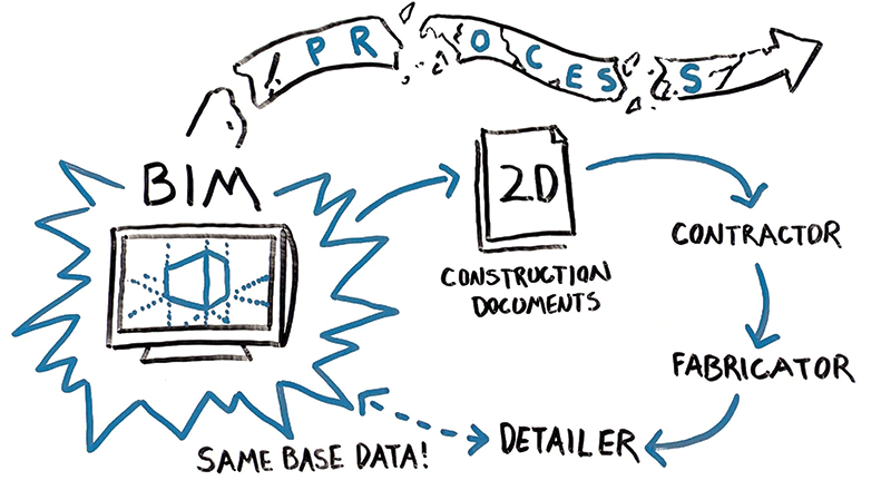
Figure 1. Traditional shop drawing process overly reliant on 2D documents.
But Some Things Have Not Changed
Sadly, though, that’s where the significant technological improvements end. The way we get from design intent to construction has remained essentially unchanged since that first day as a young engineer (Figure 1). Our use of all of this wonderful 3D rich content dies with a hand-off of 2D paper drawings for construction. Both sides of the equation benefit greatly from technology individually, but the missing link – the gap between our two processes – is hindering the true efficiency improvements technology could really bring to bear on our projects.
In 2004, I left my old firm and started out on my own. We adopted BIM in 2006 and quickly recognized its potential. As my new firm expanded our use of BIM, this gap between design and construction became more apparent. We do our work in BIM and hand off our design via 2D drawings, only to learn later that the contractor has recreated most of the original design models himself.
Schedules are generally a driving factor in most of our projects. It seems like everyone needs to get into their building quickly and the current economy has only escalated the need. One of the ways the construction industry has responded is by involving construction trade partners earlier. Identify the tasks on the critical path and get those players involved earlier. On most of our projects, that usually means getting the steel fabricator involved at some point during the design phase.
While I think we could agree that schedules have improved, it has been accomplished by taking an old, out dated process and simply making it faster, not more efficient. This is apparent by the increasing amount of RFIs and change orders we engineers have to deal with. Earlier involvement means our drawings are less developed, which translates into lots of clarifications. On our projects, early involvement typically means the fabricator is hired based on a GMP before the design is finished which has consistently resulted in change orders.
The constant parade of change orders for our steel buildings is not good for the industry, regardless of whether they’re justified or not. Owners won’t tolerate having to pony up for more cost forever when they think they have been given a GMP.
The Process Needs to Change
In 2012, we set out to change the old outdated process. We figured out a way to share our structural data, multiple times during the design phase of the project, with a steel detailing partner to shorten the delivery of steel to our projects by 8 weeks. And, we eliminated the RFIs and change orders in the process by creating the steel fabrication package during design. Problem solved, with case studies to demonstrate the savings.
The key factor here was leveraging our structural data and sharing it downstream. We could use it both to improve our productivity from analysis to construction documents; and also make downstream processes more efficient, not just faster, by eliminating the recreation of data.
Once we saw the benefit this new process brought to the construction of our steel buildings, we started looking for other building types that could leverage what we had learned from steel. Our tilt-up projects seemed to be handicapped by many of the same problems. Our analysis is done in 3D, yet the method of communicating our design is 2D. Someone else is typically responsible for coordinating the minutia of details, completing the engineer’s design intent and delivering it to the field in the form of shop drawings. And, much like our steel buildings, all of the construction phase work involves the recreation of data the engineer already has, and is subject to the same RFI and change order hazards.
Leveraging Lessons Learned
In 2014, we started looking for tilt-up design software that would address the following criteria and allow us to really take advantage of BIM:
- Working with walls as opposed to individual panels to minimize the bookkeeping while the design was changing, i.e., four walls instead of 100 individual panels
- Adding loads globally to walls and the program divides the loads to individual panels
- Adding panel geometry, openings
and embeds - Associativity of components – move a support line, and loads and embeds move with it
- Automated determination and design of the panel
- Automated generation of panel layout drawings and reinforcing drawings
- A BIM ready 3D output of the walls –
an IFC complete with panel joints and openings - Quantity take-offs that we could share with downstream users.
Tilt-Werks® satisfied all of those criteria.
So, what can you do with all of this design information to add value to your tilt-up projects with BIM?
With some careful planning of modeling and origins, the BIM you get from your steel design program can be attached to the IFC model you get from the tilt-up software. The automated panel layout shop drawings from the tilt-up software – complete with embeds and openings – could be repurposed by attaching each drawing to the inside face of the wall IFC model at its respective panel location. That puts the steel framing, panels, openings and embeds all in the same context.
As the design evolves, the steel BIM gets updated from the analysis program, and the exported IFC and panel drawings are refreshed from the tilt-up software. You could end up with something like Figure 2.
But Doug, you say, this looks like all the other images found on any company’s website on the internet. Where’s the value in another pretty picture? Not only that, this looks really tough to review and coordinate in 3D.
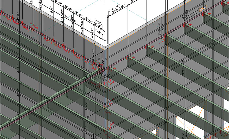
Figure 2. Complete steel and tilt BIM combined together for visual coordination.
Leveraging BIM
So, let BIM do all the work! By cutting sections at the face of the walls, coordination becomes very easy. The steel and tilt-up elements are all shown in context to one another and errors can be easily uncovered. If you set your view attributes correctly, you can see which members are on the near side of the wall (solid) and which are on the far side (dashed). If you develop an embed naming convention that distinguishes between embeds on the upcast and downcast faces of the panel, you can visually verify that the embed labeling matches the location of the steel members – before the panels get built.
In our case, we use an asterisk to identify embeds on the downcast face. For coordination, we scan the extracted elevations (Figure 3) to make sure all embeds with an asterisk have a dashed member at their location. If a solid member is found, one of the two is wrong and the correction can be made. Figure 3 is an example of a section cut with framing on both sides of the wall.
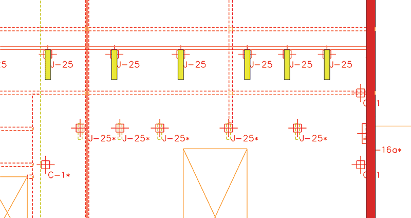
Figure 3. Using BIM to verify embeds and framing in complicated areas.
This composite BIM can also be used to check for errors as well, not just the upcast or downcast location of embeds. Because there are two analysis programs (steel and tilt-up), it’s not unthinkable that a change in one program doesn’t get picked up in the other, particularly while the design is changing. BIM is a perfect environment to do this error checking (Figure 4). This is an example where a new bay was added, the steel framing was modified but the tilt-up embeds had not been adjusted accordingly.
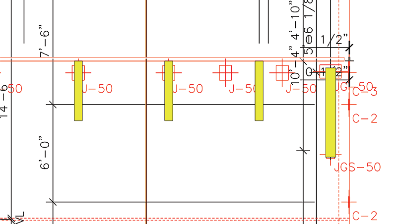
Figure 4. Using BIM to resolve coordination errors for tilt-up construction.
So, BIM can do a really great job of coordinating our steel design and tilt-up design. But, what if we take this a step further to add even more value? What if the quantity take-offs from the tilt-up software were shared with the tilt-up sub-contractor? If the take-offs are robust enough and include all of the items that the contractor needs to price the project – length of forming, gross and net square footage of the panels, length and size of reveals, quantities of embeds, tonnage of reinforcing, etc. – they could all be used at any point during the design to help monitor the cost of the structure. What contractor or owner doesn’t want to know where they stand during the design phases instead of waiting until the design is finished? At any point during the design you can provide a take-off that could easily have dollar amounts applied to it.
The Value Proposition
Some of this may seem like a lot of extra work; some of it may not. The first time or two will require some trial and error as you home in on a system that works for your office. But once set up, updating is almost automated. You are getting design information from your steel design program pushed down to your steel BIM multiple times during design, and as the tilt-up design continues to mature you can generate updated drawings, an IFC and quantity take-offs at any time.
Here’s a summary at some of the key value-add you gain by doing this extra work:
- Single source responsibility for the design and detailing. You are the EOR for the project. Your seal is on the building drawings. Who best knows how the building needs to go together. Why not leverage that knowledge and put it to good use. Do the coordination yourself and know you have everything covered. You have to review the shop drawings anyway.
- Better coordination. If you have worked in BIM (3D) before, surely you have discovered something you wouldn’t have caught in 2D until the project was in construction. Why wait for something to get caught later, regardless of who is “responsible”, and have to deal with the RFI (or change order) in panic mode during construction. Coordinate early, save time later. Leverage BIM to help with all of that work.
- Speed to market. If your tilt-up design program is able to generate the panel layout and reinforcing drawings automatically, you can easily generate a complete set of field use drawings when you issue your construction documents. Think of the time savings you can offer your client by shortening the typical construction schedule.
- Quantity take-offs. If your tilt-up software gives you robust quantities (surface areas, embeds, weights, tonnages, reveals, etc.) at any time during design, allow that information to be used downstream. This can be particularly helpful if you are working with a design/build or fast-tracked project. Everyone has their finger on the pulse of the project cost these days. Anything you could do to help with that would be valuable.
The Bigger Picture
I think we could all agree that the last seven years have been pretty tough on both the design and construction communities. Design fees are under constant pressure and it seems there is always someone willing to take a project for a lesser fee than you. Even though you know you do a better job than those other guys, trying to sell subjective benefits to a client (“better” engineering, faster response time to questions, always accessible, and just plain nice guys) is difficult at best and generally a waste of time.
However, if you can show you can add real value to a project – specifically time and/or money – now you have their attention. A difference in design fees could pale in comparison to the additional revenue an owner receives by getting in their building a month early. Leveraging BIM on your tilt-up projects is a great place to start for adding tangible value your clients will notice immediately.
By the way, if you’re doing what everyone else is doing, you’ll get paid what everyone else is getting paid. Find something your firm does better than everyone else, leverage it to the max to differentiate your firm from the rest and figure out how to translate it into real value for your clients. Hopefully, the thoughts presented here give you a decent starting place for your tilt-up projects.▪