
The Florida Hospital for Women is located on the main campus of Florida Hospital South in Orlando, FL. It is a 12-story, 430,000 square-foot facility dedicated to the health and well-being of women and new born children, with a 322-bed tower. Opened in December 2015, the facility includes 14 labor and delivery suites, 13 operating rooms for obstetric and women’s services, 72 postpartum care beds, mother-baby beds, high-risk beds and 80 neonatal intensive beds. The operating rooms accommodate robotic surgeries for obstetrics, including the da Vinci Surgical System for robotic minimally invasive surgery.
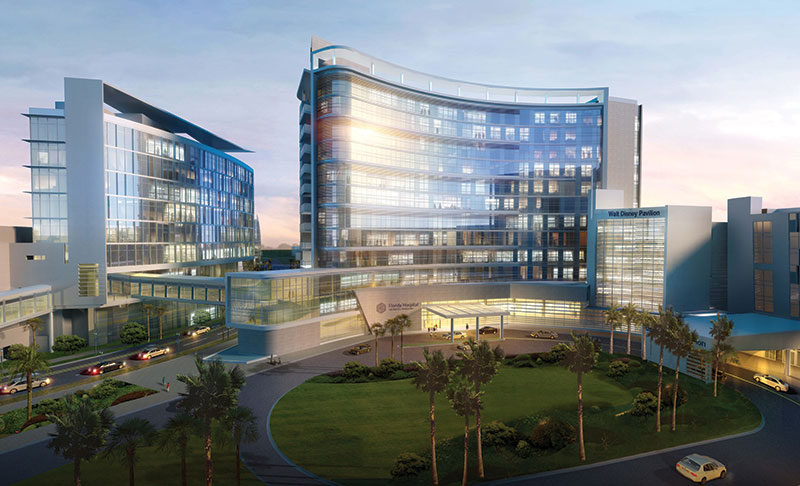
The building is situated on a tight urban site bordered by CSX rail lines on the west, the 3-story Andersen Wing, an existing 40 year old hospital building, on the north, the 10 year old 7-story Walt Disney Pavilion for Children on the northeast corner, Rollins Street, a public street on the south and the main hospital entrance on the east.
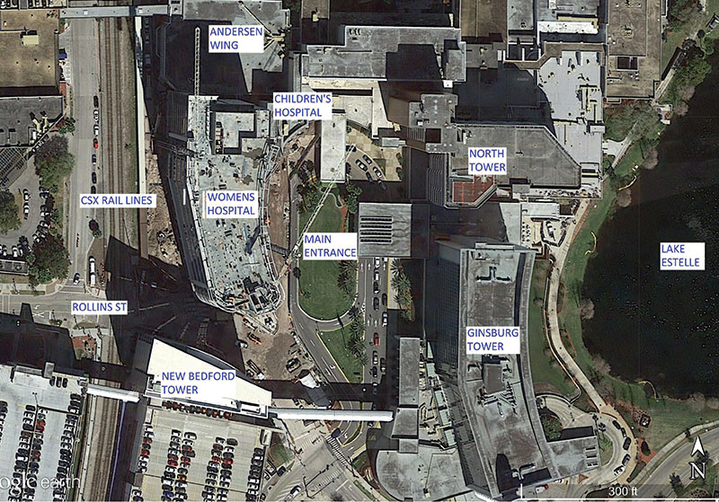
Figure 1. Campus plan.
Structural Frame
A cast-in-place concrete building was the preference of the hospital, based on their previous success with concrete construction. The benefits to the hospital include:
- Inherent fire protection
- Accommodates future modifications and changes of use, with minimal disruption to ongoing operations in a sterile environment
- Inherent ability to dampen vibrations
The project team evaluated two framing systems during the schematic design phase. Preliminary designs were prepared by Paul J. Ford & Company (PJF) for a conventionally reinforced 27-inch deep module joist and beam system (5-inch slab + 22-inch pans) and a 12-inch conventionally reinforced concrete flat plate. Post-tensioning was not considered as conventional reinforcing is more easily modified for future floor penetrations and openings required for healthcare facilities. The designs were evaluated by the team and the flat plate was selected based on the following benefits:
- Accommodated an irregular column layout dictated by the building’s unique curvilinear shape
- Minimized the structural floor depth allowing increased interstitial space for high demand MEP systems necessary for a hospital
- Reduced the overall height of the building by 12 feet, reducing the cost of the building envelope
- Simplified the form work and reinforcing steel placement
- Increased the speed of construction
Columns are typically 30 x 30 inches from foundation to roof. Interior columns from the foundation to Level 7 are 30 x 36 inches. Concrete strengths varied from 7000 psi to 5000 psi.
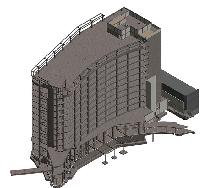
Figure 2. Isometric view of Revit model.
Concrete reinforcing steel was specified to be Grade 60 for bars up to No. 9 and Grade 75 steel for No. 10 and No. 11 bars. Specifying the higher strength steel for the larger bars eased congestion by reducing the required number of bars, and saved placement costs. The material cost for the Grade 75 bars was 4% greater than the Grade 60 bars.
The primary lateral load resisting system is an ordinary concrete shear wall system. A “blade” shear wall was required at the south end of the building to supplement the stair and elevator cores, in order to maintain torsional rotation within allowable limits.
An elevated pedestrian bridge located between the second and third levels connects the new hospital to the New Bedford Tower on the south end of the hospital. Escalators connecting the bridge lobby to the main lobby on Level 1 dictated the need for a transfer girder over the escalators. A one-story connector was included along the north east corner that connects to the existing Children’s Hospital.
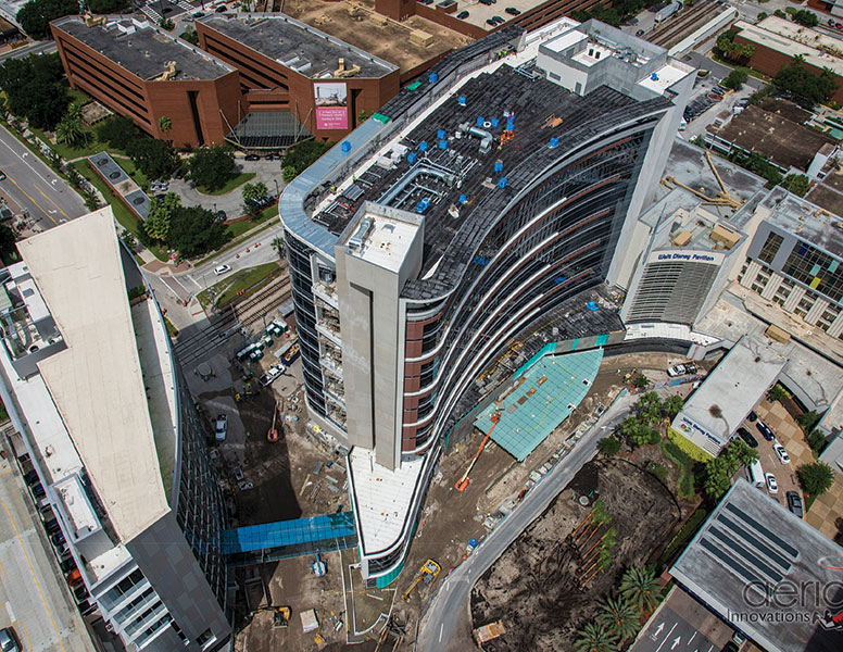
Figure 3. Progress as of September, 2015.
Vibration Study and Design
Minimizing vibrations is a design consideration in all healthcare environments in order to assure a comfortable environment for patients, and is necessary to allow uninterrupted medical procedures. All healthcare facilities must be checked for footfall induced vibrations. The heavily traveled CSX rail lines located immediately to the west of the new Women’s hospital presented a unique design challenge to the team.
Vertical vibration criteria used in the design were an ISO Operating Theater vibration criteria of 4000 micro-inches/second (mips) for patient rooms and other patient areas, and a VC-B vibration criterion of 1000 mips for the operating rooms on Level 2. A limit of 4000 mips is on the threshold of human perception. A limit of 1000 mips is suitable for micro-surgery, eye surgery and neurosurgery.
Preliminary structural calculations indicated the building structure met the 4000 mips criteria for patient rooms and other patient areas due to footfall, but did not meet the 1000 mips criteria for the L2 operating rooms. It was estimated that a 27-inch beam and slab system would be required to meet the 1000 mips criteria from footfall.
In order to measure the vibration effects from the adjacent rail lines and to conduct studies on the vibration performance of the building, RWDI was retained by the hospital. Part of that study included taking ground vibration measurements in the form of time-history accelerations and determining the vibration performance of the new hospital. RWDI created a model of the mat foundation and soil properties using the soil-structure interaction software Dyna5.4. A shear-wave velocity of 660 fps, provided by Terracon, the project geotechnical engineer, was used for the soil surrounding the foundation. The measured time-history accelerations were applied to the Dyna5.4 model and the response of the foundation was then used as an input load to a SAP2000 finite element model. PJF’s ETABS model was used to generate the SAP2000 finite element model that was modified for dynamic analysis. The velocity responses were determined at specific points in the SAP model. These records were processed by RWDI to determine the expected vibrations in 1/3 octaves for several representative trains at various locations in the building.
Three types of trains travel the rail lines; passenger, freight and heavy freight trains. The predicted vibration levels on Level 1 and Levels 3 through 12 achieved the required 4000 mps criterion. The predicted vibration levels on Level 2 achieved the required 1000 mips criterion for the passage of passenger trains and freight trains. The predicted vibration levels on Level 2 due to the passage of a heavy freight train exceeded the required 1000 mips criterion for that level.
Vibration mitigation was implemented on Level 2 by stiffening the floor system to a 24-inch deep beam and slab (12 inch slab and 12 inch pan) system.
Additional measures were evaluated to further mitigate vibration from the heavy freight trains including a base isolation system, isolating the rail lines, or constructing a deep slurry wall between the building and the rail lines. The base isolation system was not a viable option, as it was cost prohibitive. Isolating the rail lines or constructing a deep slurry wall may be implemented in the future, if deemed necessary by the hospital.
Geotechnical-Structure Iterative Foundation Design
PJF and Terracon worked closely together on the foundation design for the new facility to arrive at a system that saved two months on the construction schedule.
Four foundation systems were considered for the hospital; auger cast piles, auger cast displacement piles, a mat foundation on improved soils, and a mat foundation.
Preliminary designs were carried out for a deep foundation system with auger cast displacement piles and a mat foundation.
The deep foundation system utilized 18-inch diameter, 50-foot long, auger cast displacement piles with a capacity of 100 tons. In addition to the construction of the piles and pile caps, a 2-foot thick heavily reinforced slab was required to resist the hydrostatic pressure due to the high water table common throughout Central Florida.
The mat foundation was designed to be 5 feet thick, sufficient to resist the hydrostatic pressure and punching shear from the columns. PJF and Terracon worked together to evaluate the need for rigid inclusions under the mat to minimize overall settlement and differential settlement. The settlement for the mat without ground improvement was initially predicted to be on the order of 3 to 4 inches.
The team decided the predicted settlement was within an acceptable limit, and that further study of a mat foundation without ground improvement was warranted.
PJF and Terracan proceeded to study the mat foundation. The study was conducted based upon the following parameters:
- The mat (raft) foundation was supported on ground without deep ground improvement elements, i.e., no rigid inclusions or similar ground improvement elements were included in the analysis.
- The thickness of the mat foundation was 5 feet.
- The modulus of sub-grade reaction values, i.e., the spring constants, ranged from 6 pci at the interior of mat foundation to 12 pci at the perimeter of the mat foundation.
- Four iterations of calculations were conducted between PJF and Terracon in order for settlement results to converge between the structural model and geotechnical model. The structural engineer utilized SAFE and ETABS for its analyses, and the geotechnical engineer utilized PLAXIS for its analyses.
The results of the study are summarized as follows:
- The total settlement of the mat foundation was predicted to be in the order of 2.5 inches at the interior core area at the patient elevators to 0.90 inches along the east edge of the mat.
- Approximately 25% of the expected total settlement will occur due to the weight of the mat prior to the casting of the Level 1 structural slab.
- The expected differential settlement in the mat was a slope rate of 0.002 or L/500.
- The settlement of the structure along the existing Anderson Building and Disney Pavilion was expected to in the order of 0.75 inches to 1.50 inches.
- The maximum contact pressure below the mat foundation was 3800 psf.
The calculated settlement values were conservative and are on the upper bound of the expected actual values based upon previous experience with similar projects.
The project team concurred that the settlements were within acceptable limits.
The three story areas of the building on the south and east elevations were supported by shallow foundations. Construction of these areas of the structure was phased to occur simultaneously with the construction of the final three levels of the tower, in order to minimize the risk of differential foundation settlement.
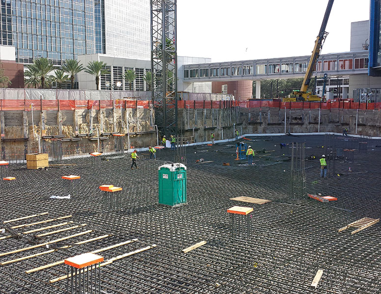
Figure 4. Mat preparing for concrete placement.
Conclusions
Measurement during construction indicated the overall settlement of the mat averaged about 1 inch with minimal differential settlement. The majority of the settlement occurred during construction of the building frame, as predicted.
Schematic design of the new Florida Hospital for Women started in April, 2012. Construction broke ground on January 9, 2013. Concrete for the mat foundation was placed on February 8, 2014 and the concrete frame topped out October 31, 2014. The hospital opened in December, 2015.
The Florida Hospital for Women introduces a whole new era of high-technology care for the women of Central Florida.▪
Project Team
Structural Engineer of Record – Paul J. Ford & Company
Owner – Florida Hospital Office of Design and Construction
Architect – HKS
Gerneral Contractor – Brasfield & Gorrie