
The U.S. Department of Transportation has determined that the country has too many existing bridges that need replacing or upgrading, rehabilitating or retrofitting. At the end of 2014, according to the National Bridge Inventory, more than 145,800 highway bridges are listed as structurally deficient or functionally obsolete; this is about 27% of all bridges based on total bridge deck areas. In some states, the situation is even worse; for example, in California the deficient bridges are 34.6%, and in New York State they are 59.8%!
The existing infrastructure is getting old, not only because of the years of service, but also due to the complex modernization of transportation. Regardless of the desire to improve infrastructure, the allocated funding cannot be sufficient to replace or repair and upgrade so many structures. Therefore, using efficient and economical solutions is essential for the better use of the limited funding available. In some cases, old bridges have historical significance that makes it even more necessary to consider retrofit in lieu of replacement.
The most typical deficiencies for old bridges are usually one of the following: insufficient live load capacity, narrow traffic lanes, low clearance, need for more traffic lanes or shoulders, unsafe structural materials or connections. In most cases, there is a combination of two or more of these items. While the need for additional traffic lanes can sometimes be addressed with a new parallel bridge, most of the other issues require structural modifications to, or complete replacement of, the existing structure.
Steel bridges are relatively easy to modify, reinforce or widen. One additional advantage of such bridges is that many built during the period from 1920 to 1960 incorporated the strongest available steel at the time of construction. For example, the San Francisco – Oakland Bay Bridge, completed in 1936, had higher-strength nickel (Grade 380 MPa) and silicon steel (Grade 311 MPa) in the East Crossing, accounting for 62% of the steel used for the entire bridge and 72% of its cantilever section. Even the carbon steel used in this bridge had strength (Grade 255 MPa) comparable to today’s ASTM A36. The same bridge had high-strength cable steel (Grade 828 MPa) for its West Crossing suspension cables.
The use of higher-strength steel, along with the fact that many of these bridges have served transportation needs well for decades, suggests that it would be more efficient to strengthen and modernize such existing structures, rather than demolishing and replacing them with new structures. This article discusses modification options for reinforcing existing bridges, utilizing the specifics of their static systems. These options are for steel-framed bridges; however, most of them are also applicable in principle for concrete bridges.
Replacing Existing Deck with Lighter System
When it is required to add more live load capacity to an existing structure, the conventional way for retrofitting is to reinforce all elements of the bridge that need strengthening. This involves substantial material, labor and time, making this method relatively inefficient. If, for example, the bridge has to be upgraded for an additional 25% load capacity, it means that all elements have to be reinforced with added steel plates or other shapes, using welding or high-strength bolting to connect them to the existing bridge members. To comply with the required 25% strengthening and to compensate for the added self-weight, it will likely require a roughly 35% increase of the cross section (and weight) for all existing bridge elements.
A more efficient approach is to replace the usually existing reinforced concrete slabs with lighter systems such as orthotropic steel decks, thus reducing the self-weight of the bridge. This approach was used very successfully in 1978 to 1986 on the re-decking of the George Washington Bridge (New York) and the Golden Gate Bridge (San Francisco). This can reduce the dead load of the deck, “buying” extra structural capacity or relieving overstress situations. This technique would make foundations easier to upgrade, or might even circumvent strengthening of piers and foundations entirely.
Generally, such replacement with a steel orthotropic deck provides a savings from 1.38 to 2.65 MPa (140 to 270 kg/m2) in the self-weight of the structure; this then becomes an extra live load allowance. A detailed study of this approach finds the savings to be approximately 35% of the original bridge weight. For the George Washington Bridge, it was 43%; for the Golden Gate Bridge, it was 32.5%. Even more efficient are substitutions of the old concrete deck with extruded aluminum deck panels, or more recently, with sandwich plate systems (SPS). These even lighter deck systems produce a weight savings of up to 60%.
Converting From Simply Supported to Continuous Spans
Considering that many longer-span bridges are multi-bay simply supported trusses or cantilever trusses, one efficient and relatively simple method of reinforcement is to transform them into continuous truss systems. This approach consists of interconnecting the adjacent simple spans and converting them to a continuous system on four, five or more spans depending on the desired length between expansion joints.
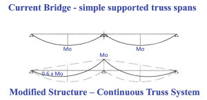
Figure 1
The improvement in capacity is a result of “moving” the maximum bending demand (Mmax = wL2/8) from the center of each span to the much shorter zone at the middle support (Figure 1). In addition, engineers can use a higher depth of the continuous truss at the middle support zone, reducing the chord loads. An example is shown in Figure 2, which comes from a study for strengthening an existing bridge at Healdsburg, California, by transforming two single-span through-trusses into a two-bay continuous truss.
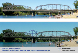
Figure 2
It should be noted that such transformations require careful analysis of all elements of the bridge, including the piers and their foundations, which might also require reinforcing. For example, the middle support of a two-bay continuous truss will be subject to higher loads, not only because of the increased capacity triggered by the retrofitting, but also because of the increased reaction at the middle support of a continuous system. Furthermore, the forces in the bottom truss chords near the middle support of the continuous system are changing from tension to compression, which may require additional modifications.
The effect of converting several simple spans into a continuous truss system is even more significant, as the bending moment demands (and related chord axial forces) are smaller along the entire length of the transformed system compared to the existing simple spans. The moment demand is reduced from 85% to 27% of the maximum moment (from uniform loads) for the simply supported spans, depending on the section location (Figure 3). Additional savings may be achieved through careful configuration of the additional truss members at the zones of support, adding higher “nodes” at the supports to the originally flat trusses with parallel top and bottom chords, thus further reducing the axial force demand for the chord members within these zones.
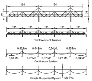
Figure 3
Reinforcing Existing Cantilever Truss Systems and Arch Bridges
Cantilever truss systems are typically three-span bridges consisting of two side spans (anchor arms), two cantilevered portions extending toward the center, and an interconnecting “suspended” central portion. This system was very popular at the end of the 19th and beginning of the 20th centuries, and allowed engineers to achieve the longest central spans for that time – up to 1800 feet (549 meters) (Quebec Bridge, 1917).
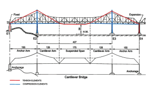
Figure 4
A rational modification for these old bridges is to add a cable-stayed type of reinforcement utilizing the middle bridge supports. The added cable-stayed system introduces pre-stressing upward forces at the tips of the cantilever arms (Figure 4) and relieves the existing system of a significant portion of the vertical loads. These upward forces, opposite to the forces in the original schemes, reduce significantly the stresses in the existing system, providing additional load capacity. The “cable-stayed” reinforcing can be pre-stressed to about 75% to 85% of the dead load reactions at the main span cantilevers, therefore relieving the existing cantilevered structure of about 60% of the total loads.
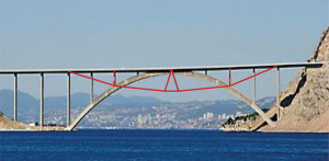
Figure 5a
The same basic concept can be used for strengthening existing arch bridges. The most simple and efficient option is to add suspension-type supporting systems below the deck (Figure 5a). This is a possible solution regardless of whether the arches are above or below the traffic deck, as long as there is sufficient clearance for the additional structure. In this option, the suspension catenary system has vertical posts in compression, unlike regular suspension bridges with vertical cables in tension.
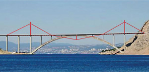
Figure 5b
In cases where there is insufficient clearance, a cable-stay system developed both above and below the deck can be the most efficient solution (Figure 5b). This option requires adding pylons at the arch supports and, if necessary, reinforcing the piers below the deck at these locations.
General Considerations
These methods have several advantages when compared to traditional reinforcement of existing bridges:
- They reduce the strength demand on almost 100% of the bridge elements, and thus increase the available live load capacity.
- The added elements can be practically independent of the existing elements, allowing for much easier retrofitting details and construction sequence.
- Construction work may be done with minimal impact on existing bridge traffic.
If necessary, some members can be additionally strengthened by judiciously adding plates, channels or other shapes, connecting them with bolts and/or welds. Moreover, compromised original rivets can be replaced with high-strength bolts.
When an enlargement of the bridge deck is necessary, the construction retrofitting is more complicated; however, even for these conditions, the upgrading is simpler and faster than using traditional methods.
Depending on the specific conditions in a bridge reinforcement project, the engineer may decide to combine modification of the superstructure and replacement of the deck with a lighter system.
Conclusion
When considering replacement of a deficient bridge structure, the owner or local transportation department should always consider possible alternative options for reinforcement. Strengthening an existing structure is a challenging task, and while many engineers would prefer to work on a “clean” new replacement structure, upgrading as described above may provide significant savings in costs, construction materials and time. Even more important is the reduction of the “carbon footprint” by avoiding the demolition of the existing bridge and significantly reducing the number of new elements used in comparison with an entirely new structure.
As the number of deficient structures continues to grow, the best structural project from a sustainability standpoint is the one that uses the minimum material and total energy. Therefore, a retrofitted structure is by definition more sustainable (and environment-preserving) than an entirely new replacement structure.▪
References
National Bridge Inventory, US Department of Transportation, December 31, 2014.
UNITED STATES STEEL, The San Francisco – Oakland Bay Bridge, 1936
Orthotropic Bridges. Theory and Design, The J.F. Lincoln Arc Welding Foundation, Second Edition March 1987, p. 2-20 and p. S-4 to S-6.