
On April 9-10, 2015 the Building Information for Modeling Masonry (BIM-M) Initiative held their first Symposium in St. Louis, MO at the St. Louis Masonry Center. Since the beginning, the initiative has been following its mission statement:
To unify the masonry industry and all supporting industries through the development and implementation of BIM for masonry software to facilitate smoother workflows and collaboration across all disciplines from owner, architect, engineer, manufacturer, mason, contractor, construction manager, and maintenance professionals.
While the BIM-M Initiative has been progressing for over two years, many structural engineers may not have been aware of this major effort. This article provides some of the highlights of BIM-M and the symposium, and their relevance to structural engineers. It is important to remember that the term BIM represents both an object (a model), and a process (modeling).
Why BIM-Masonry? To give masonry an opportunity to compete with other building materials while simultaneously improving the industry. The BIM-M Initiative began in 2012 and represents the masonry industry in the United States and parts of Canada.
The Symposium opened by welcoming the many architects, structural engineers, manufacturers, contractors, suppliers, supporters, and guests. The audience learned that Phase II (Development) based on the original roadmap has been completed. Phase II contained four projects; 1) Masonry Unit Model (MUD) Definition, 2) Masonry BIM Benchmark, 3) Masonry Wall Model Definition, and 4) BIM-M Contractor Input. BIM-M also announced that an updated Roadmap, a report for developing and deploying BIM for masonry, has now been posted on the website (www.bimformasonry.org). The proposed timeline for Phases III and IV begins now and will run until the end of 2017 with the completion of Generation 1.
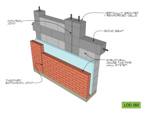
Figure 1. LOD 350 for design.
What is Generation 1 BIM-M? Generation 1 is defined as the conceptual termination of the BIM-M Initiative’s initial efforts to make masonry more accessible to architects, structural engineers, masons, contractors, manufacturers, and owners using BIM. Some aspirations for what Generation 1 will include are:
- Masonry unit database accessible to all BIM users.
- Masonry wall definitions for Level of Development (LOD) with standard details.
- BIM software upgrades that achieve LOD 350 or greater for design (Figure1).
- BIM software that allows contractors to achieve LOD 400 or greater for construction purposes, and can detect clashes with specific masonry features (bond beams, grouted cells, shelf angles, etc.)
- BIM software upgrades that will operate with other masonry specific software.
- New and/or improved design tools (software upgrades, add-ins, plugs-ins) that provide for modularity, early project pricing, and masonry detailing.
Masonry Unit Model Definition
Over the course of the last two years, the BIM-M Masonry Unit Working Group, led by Jeff Elder, SE, Interstate Brick, HC Muddox and Western States Clay Products developed a spreadsheet to represent the majority of data parameters and specification information to be used by BIM software developers for the design, purchasing, shop drawing and sustainability of clay, CMU and cast stone. This data set was based upon geometric and material attributes provided by numerous manufacturers. The physical properties entity includes attributes for both mechanical properties and thermal properties of masonry units, including; weight, density, compressive strength, modulus of elasticity, modulus of rigidity, shrinkage coefficient, coefficient of thermal expansion, and creep coefficient.
For structural engineers, this means there will be on-line access to geometrical and material properties for modeling masonry in BIM software as well as for analytical programs that interact with BIM.
BIM-M Benchmark
The original intent of the BIM Benchmark project was to focus on software capabilities and to understand the role of software in the masonry industry at all project phases. The Phase II project, led by Russell Gentry, PE, Project Manager, Digital Building Laboratory, Georgia Institute of Technology, extended this scope to focus not only on software but also on BIM processes, that is, how masonry stakeholders use BIM or other tools. The primary goal was to develop a vision for “future state” processes that can take advantage of the Generation 1 BIM-M software. The original proposal called for the analysis of three project types: brick/CMU, structural masonry, and complex masonry. Georgia Tech, along with the University of Pennsylvania, completed nine building case studies of various building types. The Benchmark Project focused on three areas:
Task 1 – Framework Development
Task 2 – Process Documentation
Task 3 – Process Model Evaluation
For structural engineers, this will lead to better interaction between analytical programs and BIM modeling during design and construction.
Masonry Wall Model Definition
This project is at the core of masonry BIM and is managed by Jamie Davis, PE of Ryan Biggs/Clark Davis through the TMS BIM Committee. Because masonry BIM is a computational model of masonry construction, and masonry walls are the fundamental assembly in masonry construction, it is critical that the data representation of the masonry wall support all of the functionality that is envisioned for BIM-M. Currently, it is simply not computationally practical for BIM software to track individual masonry units in an entire building. Therefore, the masonry BIM data structure must include the definition of wall types, and must provide the means to map these wall types onto regular and irregular regions on wall surfaces. The working group discussed and suggested a level of development (LOD) of 350 for architects and structural engineers.
Also, one of the four new tasks for Phase III is to develop and publish a Best Practices Guide for Modeling of Masonry using Autodesk Revit in cooperation with The Masonry Society (TMS). The Guide has a three-fold purpose, including: 1) informing users on how current BIM tools may be used to model masonry, 2) to define what collaboration and modeling tools are lacking, and 3) to create a wish-list of modeling tools that would be helpful to the industry.
Structural engineers will have more efficient modeling tools that will carry over into the analytic programs.
BIM-M Contractor Input
It has been clearly determined that mason contractors and masons will benefit from BIM-M. In this project, BIM-M proposes that mason contractors explore in greater detail the potential benefits of BIM, and document their current work processes and their use of software in current practice. Input from general contractors will be solicited as well, to identify areas where general contractors desire interaction with masonry construction in their BIM models – for example, in coordination of masonry with structural, mechanical and other building systems for clash detection.
The keynote speaker was Will Ikerd II, PE, from Ikerd Associates, Dallas, TX. He also represents the BIM Forum and chairs the SEI BIM Committee. He began his presentation by stating BIM is about giving a “common vocabulary”. Will discussed the various levels of development (LODs). He pointed out that, in 2008, an AIA document for the first time defined LODs. In giving his opinion, he described the LODs simplistically as:
- LOD 100 – symbolic
- LOD 200 – approximate
- LOD 300 – specific
- LOD 350 – detailed (interfaces with other building systems)
- LOD 400 – detailing and fabrication
Will announced to the audience that the Level of Development (LOD) Specification is a reference that enables practitioners in the AEC Industry to specify and articulate with a high level of clarity the content and reliability of Building Information Models (BIMs) at various stages in the design and construction process. Shown on the cover of the 2014 LOD Specification are the various LODs for masonry (Figure 2). The specification is a free download from store.bimforum.org.
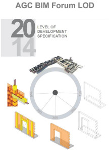
Figure 2. Cover of 2014 LOD Specification.
Two specific presentations came from BIM-M consultants who are providing modeling tips and tricks for masonry, which will be released later this year as Best Practices Guide. BIM-M has tasked them with demonstrating the modeling of masonry using current software and recommending future improvements.
Best Practices #1
Presenters from the architecture and engineering firm Integrus Architecture from Seattle, WA included Mike Adams, BIM Manager; Morgan Weise, EIT; and Clint Bailey, AIA showed some features of what they will be contributing to the Best Practices Guide.
The most common masonry elements in BIM are walls which are always modeled in three-dimensions. However, many masonry details are presently handled in two-dimensions. The current strategy for creating drawings is to take the three-dimensional model and slice it to reveal the information that is desired.
Integrus demonstrated the three-dimensional detailing function. Because these views are live or three-dimensional, any changes that are made in them affect the rest of the model. For example, BIM software typically includes a number of pre-made families including openings with arched tops. In the BIM-M project, Integrus used three-dimensional sweeps (model elements) to represent stone sills, lintels, and quoining.
Another example dealt with representing reinforcement in models. The current advantages of two-dimensional reinforcement are detail line, components or groups; fast to make changes; and easy to export details from project to project. The current disadvantages are an absence of embedded information (no clash, no scheduling and no tagging), everything fits and no warnings as things move. Integrus noted that the current advantages of modeling reinforcement in three-dimensions are improved coordination, accurate schedules, tagging, and correct warnings when things are moved. The current disadvantages are longer modeling time, all walls are treated equal and an enlarged model file size (Figure 3).
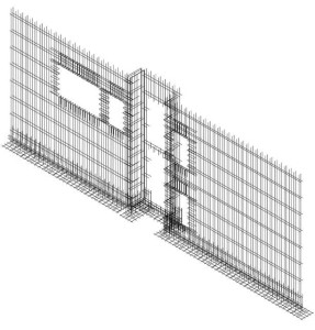
Figure 3. Three-dimensionally reinforced wall.
Best Practices #2
The second BIM-M consultant was Shawn Zirbes, Cad Technology Center (CTC) from Minneapolis, MN. Shawn used the BIM Forum LOD 2014 Level of Development Specification and displayed the BIM-M for Masonry LOD examples for levels 300, 350 and 400. Shawn showed a structural model of the Brick Office Building with brick on CMU backup on a portion, and brick with metal stud backup on the remaining portion. The model was then split into an exterior shell model and an interior model. For both the brick with block backup wall and brick with metal stud backup wall, Shawn presented the LOD 300 with a plan and section view, respectively. He then displayed LOD 350 for the block (CMU) backup showing the grouted cells where the CMU wall is placed in a structural model and the remaining wall layers (brick veneer, wall ties and drainage panel, rigid insulation, and air barrier) are modeled as individual wall types in an architectural model (Figure 4). With respect to the LOD 350 for metal stud backup, all wall layers (brick veneer, wall ties, rigid insulation, air barrier, sheathing, metal studs and gypsum board) are modeled as individual wall types in an architectural model. Anchor type placement was shown for both systems in plan and sectional view. Brick patterns were developed as model hatch patterns showing running bond (primary), stacked bond and Flemish bond. This allows for architects and structural engineers to check modularity in their designs.
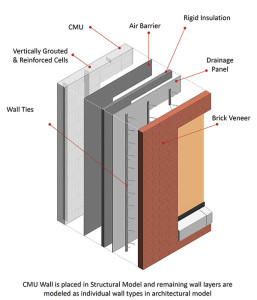
Figure 4. CMU wall in structural model and remaining wall layers in architectural model.
Contractor Software for Use by Engineers
Bill Pacetti and Bill Pacetti, Jr., from Tradesmen’s Software, Inc., Morris, IL, presented their software. This software was developed for mason contractors but has features that could be valuable to architects and structural engineers including cost estimating, evaluating aesthetics by varying units, checking dimensions for modularity of units, and more.
BIM-M and Structural Software
In Phase III, BIM-M will start a new project associated with structural engineering. In an attempt to improve modeling techniques and interoperability of analytical software with BIM authoring tools, consultants will be selected to examine various software packages and their use with BIM packages. Structural engineers interested in being considered for this work should contact BIM-M through its website.
While this article has provided an overview, free downloads of videos, presentations and reports for BIM-M are available from the website also.▪