
A Fundamental Discussion
Nearly every day in our careers as structural engineers, we consider the following equations:
Mn = Asfy(d-a/2), Mn = FyZx
Readers will no doubt recognize these as the nominal flexural strengths utilized in beam designs for reinforced concrete and steel, also known as (among other things) the flexural limit state. While there are variations reflecting unbraced lengths, the presence of compression reinforcement, axial loads and other considerations, these are the fundamental relationships. What exactly does this mean?
Structural engineers understand that the capacities represented by these equations do not correspond to the loads that we actually expect the members to see during a typical service condition. Rather, these are the approximate magnitudes of loads that the members would experience in the unlikely event that they are pressed toward ultimate failure. This will hopefully never occur for members that are part of the ‘gravity’ system. Likewise, this will hopefully not occur for a large but rare transient event in members that are part of the ‘lateral’ system. Either way, the fundamental objective is to ensure that designs have φMn greater than Mu, the maximum flexural factored load effect.
Now consider the ‘middle ground’ in this scenario – the flexural behavior that occurs between zero load and a condition where Mu equals Mn. Doing so offers a glimpse of basic nonlinear behavior and the formation of flexural mechanisms that hopefully reflect stable and ductile performance.
For the concrete beam scenario, at a load equal to Mn it is assumed that the reinforcement has yielded in tension following the idealized elastic-to-plastic relationship, with a constant stress equal to yield stress (fy) with a strain somewhere beyond the yield strain of approximately 0.00207 (for Grade 60 bars). It is also assumed that the concrete acting in compression has reached a strain of 0.003 and that at this point, it is theoretically being crushed at its extreme compressive surface. To understand what has happened in the beam while reaching this point requires developing a series of calculations reflecting various levels of reinforcement strain, from zero all the way up to the net tensile strain (εt) which occurs at a theoretical load of Mn.
For each one of these calculations, it is possible to develop resultant forces based on relative strains in the tension steel and the concrete compression zone, and a moment-couple relationship based on the distance between the resultant forces. This relationship is relatively simple, since we know from statics that the resultants of tension and compression must always be equal in magnitude and opposite in direction. While many theories have led to the development of models reflecting the distribution of stress in the concrete compression zone, assuming a uniform compression zone as prescribed by ACI 318 is valid and greatly simplifies the calculation, enabling the a/2 portion of the equation previously shown.
For each series of calculations, the curvature value is simply taken as the strain in flexural reinforcement divided by its distance from the theoretical neutral axis. Plotting the values of Mn and curvature yields a load-deformation (curvature) relationship, an example of which is shown in the Figure.
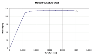
Moment vs. curvature relationship for reinforced concrete beam.
Among the interesting things observable in this figure is that nominal moment capacity is nearly reached at the point where the tensile reinforcement first yields – long before the member reaches is ultimate capable curvature at Mn. What does this mean in a practical sense? Observe that the nominal flexural strength is approximately 240 kip-ft and that this particular member reached this capacity at a curvature just beyond 0.0002/in. However, the member was able to sustain this load to a curvature nearly five times this value, thereby demonstrating the ductile behavior toward which the codes are geared. This exercise demonstrates that failure of this member would be preceded by deformations likely to present a serviceability issue, thus giving occupants warning of trouble.
As an interesting exercise, consider increasing the area of reinforcement to the balanced or over-reinforced condition. The results will demonstrate a smaller ratio of maximum capable curvature vs. yield curvature, which grows ever smaller as the amount of reinforcement increases. This demonstrates the pitfall of simply adding reinforcement to improve strength.
It is also worthwhile to consider seismic response. The Figure demonstrates the potential for favorable hysteretic behavior as the area under the curve is proportional to the energy release occurring through each cycle of flexural load and rotation. If the reinforced concrete is detailed correctly, this is a favorable, stable and controlled method for dissipating energy during an earthquake, thereby preventing it from becoming manifest elsewhere. The same holds true for steel beams, provided that they are appropriately sized and detailed to promote fundamental material nonlinearity, as opposed to other forms of ‘macro’ nonlinearity such as global or local buckling.
Observations of the projected theoretical behavior of mechanisms such as this are worthwhile. They offer a glimpse into the basis for code provisions that we often take for granted.▪
A similar article was published in the Structural Engineers Association-Utah (SEAU) Monthly Newsletter (September 2011). Content is reprinted with permission.