
Cold-formed steel (CFS) trusses can be an economical framing option for many buildings, and are often the most economical option for those having a steeply sloped roof. Some advantages of CFS trusses are that they have an excellent span-to-weight ratio, can be shop-fabricated into custom shapes, and are non-combustible. Despite these advantages, the use of CFS trusses on inhabited building projects funded by the Department of Defense (DoD) can be challenging because of the requirements imposed by Unified Facilities Criteria (UFC) 4-010-01, DoD Minimum Antiterrorism Standards for Buildings.
One of the primary design strategies of UFC 4-010-01 is to increase the standoff distance between buildings and potential explosive threat locations. In 2012, UFC 4-010-01 was amended to correlate the standoff distance at which no analysis for blast loads is required with the exterior wall and roof construction type. Buildings constructed of heavier and more robust materials, such as reinforced concrete or masonry, are permitted to have smaller standoff distances than buildings constructed of lighter materials, such as wood or CFS studs, as long as the structural design complies with UFC-prescribed detailing requirements. Provisions for several wall and roof systems are included in the UFC, but any wall or roof type that differs from the prescriptive requirements must be analyzed for blast loads. One roof framing system not explicitly addressed is CFS trusses with metal roof deck.
CFS trusses are typically constructed of proprietary light-gauge steel shapes and designed using proprietary tools developed by CFS truss designers and manufacturers. The design of CFS trusses is generally delegated by the Structural Engineer of Record (SER) to a specialty engineer familiar with these proprietary member shapes and design tools. However, it is the responsibility of the SER to define the truss performance requirements – including the blast loading requirements for DoD projects – such that the specialty engineer can design the individual trusses and overall truss system including bracing, bridging, connections, etc. For the SER, understanding and communicating the loading requirements so that the project can be bid appropriately is an important part of the design process. This article documents the method employed to address this challenge for one project and describes the analyses performed along the way.
Project Overview
The example project is a two-story, 11,800-square-foot, multi-use facility with retail, food service, and meeting spaces. The building was constructed using CFS roof trusses, composite steel and concrete floor framing, exterior load-bearing reinforced masonry walls, and shallow foundations (Figure 1).
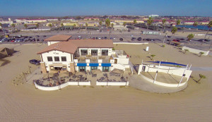
Figure 1. Completed multi-use facility.
The client desired a new facility to match the existing architecture of the area, which meant a Mediterranean-style building with a sloped roof. Typically, CFS trusses would be an economical framing choice to achieve this slope; however, the mandated DoD requirements warranted further investigation.
The standoff distance to the controlled perimeter was more than 200 feet, and the standoff distance to parking, roadways, trash containers, and other obstructed spaces was nearly 100 feet. While UFC 4-010-01 allowed for smaller standoff distances based on the chosen exterior wall system, reducing the standoff distance would have significantly increased the blast loads on the roof structure, and therefore its cost.
Specifying CFS Trusses for DoD Project
CFS truss designers are very familiar with code-mandated environmental forces such as dead, roof live, snow, and wind loads. Software written by product manufacturers or third-party vendors is available that will size thin-wall steel members and their connections to resist these static loads based on design procedures established by the American Iron and Steel Institute (AISI). However, design for the high-magnitude, short-duration loads associated with explosives is less well-established.
The blast load analysis requirement introduced by UFC 4-010-01 placed the SER in a difficult position when specifying blast loads for the CFS trusses of the subject project. One option was simply to delegate the blast load analysis of the CFS trusses to the manufacturer, but this would assume that the manufacturer has engineering personnel who could properly apply these requirements and bid the truss package accordingly. If incorrect, such an assumption could lead to incorrect bids and costly delays in the submittal review process.
An alternative approach, which was utilized for this project, was to conduct a generalized dynamic analysis such that an equivalent static blast load could be included in the delegated design performance specification. Ideally, this approach would enable the truss manufacturer to size truss members properly at the bid phase and estimate costs accordingly.
Blast Effects Analysis of CFS Truss
Conducting a generalized dynamic analysis such that an equivalent static blast load could be included in the delegated design performance specification requires an approach that approximates the global response of the truss while still accounting for localized phenomena. The approach ultimately consisted of quantifying the external forces applied (i.e., blast load) and the mass, stiffness, and controlling limit state(s) of the system (i.e., the truss model) such that a dynamic analysis could be conducted.
Blast Load Considerations
Blast loads applied to roof structural components are generally not uniform along the length of the truss, particularly when the span is oriented perpendicular to the direction of shock front propagation. A method of simplification espoused by UFC 3-340-02, Structures to Resist the Effects of Accidental Explosions, allows the blast load to be idealized as uniform along a component’s length by summing the effects of the incident overpressure and drag. It should be noted that this involves two assumptions:
- The shock wave is not reflected by the roof surface, but rather “drags” across it. For sloped roof systems, this may not be valid if the angle of incidence is less than 90 degrees.
- The wavelength of the blast wave is not significantly shorter than the length of the truss. In this case, a uniform load is not a valid idealization of the blast loading.
Blast loads consist of positive and negative phases. In many cases, ignoring the negative phase and simply analyzing the structural component for the positive phase will generate a conservative component response. However, for situations where the structural component is lightweight and/or the blast loading is characterized by a long positive-phase duration relative to the period of the response mode considered, as is often the case for CFS truss roof systems, consideration of the negative phase may dictate the peak response of the component. Therefore, it was important to consider both “positive phase only” and “positive plus negative phase” scenarios.
SDOF Truss Model
Based on the lack of information concerning individual truss properties, a single degree-of-freedom (SDOF) model was utilized to model a generic truss in order to generate an equivalent static blast load. The use of an SDOF truss model implied that the load could be idealized as uniform, a single degree of freedom could adequately represent truss response for the idealized blast load, and a corresponding resistance function could be generated that would capture the controlling limit state.
The assumption concerning the controlling limit state of a CFS truss is important in selecting a suitable response limit. SDOF response limits applicable to DoD construction are documented in PDC-TR 06-08, Single Degree of Freedom Response Limits for Antiterrorism Design; however, there are no response limits indicated for CFS trusses. In the absence of formalized guidance, the SDOF response limits for open web steel joists were assumed. Both systems are trusses, and thus rely on the axial strength and stiffness of constituent members to span large distances. However, tensile chord yielding can be difficult to achieve in practice for CFS trusses, because they are generally much deeper and will have longer web members in compression than open web steel joists. Thus, it was considered reasonable, although perhaps conservative, to assume the failure mode for most CFS trusses would be some form of web member buckling. A ductility ratio (maximum deflection to yield deflection) of 0.9 for heavy damage was used as recommended in PDC-TR 06-08 for an open-web steel joist web member buckling response limit.
Given a uniform load normal to the truss top chord, the point of maximum truss deflection was assumed to occur at mid-span and the deflected shape was assumed to match that of a simply supported beam subjected to a uniform load. A closed-form expression for peak truss deflection that is a function of time, blast load pressure-time history, and the fundamental period of the truss, Tn, was derived and used to develop shock response spectra (SRS) for truss inbound and rebound response. The developed SRS assumed that the inbound and rebound stiffness of the truss were equal. An example of SRS developed for a “positive phase only” loading is shown in Figure 2, where the deformation response factor, Rd, is equal to peak truss deflection divided by the truss deflection induced by a statically-applied peak blast pressure, p0.
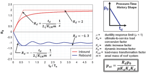
Figure 2. Example of shock spectra for inbound and rebound truss response.
To determine Tn, the mass and stiffness of each truss were required. While mass could be assumed as the roof system dead load tributary to the truss, the stiffness was unknown at the time of performance specification development. As such, the equivalent static blast load was defined in the performance specification as a function of truss spacing, s; truss length, L;
and truss stiffness, k – all properties that the truss manufacturer would readily know.
Truss stiffness was defined as the initial slope of the load-deflection curve, where “load” is the summation of the uniformly-applied vertical load tributary to each truss, and “deflection” is the maximum truss deflection corresponding to the “load”. The three parameters that varied (s, L, and k) were collapsed into a single variable, x = (sL/k)0.5, and a table was included in the performance specification that correlated different ranges of x with an equivalent static blast load. Thus, the truss manufacturer could determine the equivalent static blast load to be applied to each individual truss based on x. The adjustment factors Ka, Ks, and Kd shown in Figure 2 were set equal to 1.7, 1.05, and 1.19, respectively – consistent with those currently used for open web steel joists in SBEDS – to provide an allowable load to the truss manufacturer. In addition, the performance specification stipulated that the tributary dead load be applied concurrently with the equivalent static blast load.
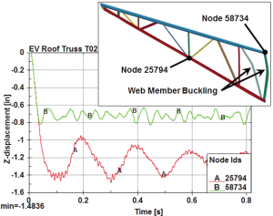
Figure 3. Nonlinear dynamic FE result for selected roof truss.
Alternatively, expressions that envelope the SRS could be derived and used to communicate the equivalent static blast load, pst, to the truss manufacturer. For the case shown in Figure 2, pst is simply 10p0td / xm0.5 for pst and m in pounds per square foot, p0 in pounds per square inch, td in milliseconds, and x in (in3/lb)0.5.
In addition to the global response of the truss, the non-uniform and time-varying nature of roof blast loads may serve to excite localized response modes of individual components, particularly the flexural response of the top chord, and should be considered in performance specification development. For this particular project, it was shown that because of the relatively short spans of the top chord and the use of a self-drilling screw attachment at every rib, the top chord was able to maintain its axial load-carrying ability under the given load between panel points.
Similarly, web member connection requirements can be provided to prevent premature connection failure due to excited localized response modes. Using the ultimate resistance of the specified roof deck and the axial capacity of the web member in question, an upper-bound force requirement can be derived and included in the performance specification. This requirement is particularly important if a higher-fidelity analysis is conducted for the CFS trusses, as will be shown below.
Finally, the stability of the trusses in three dimensions should be considered. Typically the top chord is braced by the steel roof deck and the bottom chord by intermittent braces. For this project, because an elastic response of the truss was assumed, no additional stability requirements were included in the performance specification.
Finite Element Truss Model
At the construction phase, truss designs were submitted by the truss manufacturer for review. For a select number of trusses, the delegated design performance specification requirements were so restrictive that an alternative means of analysis was requested by the truss manufacturer. As such, a transient nonlinear finite element (FE) analysis was performed for a representative truss that was among the stiffest, yet had a relatively large tributary area.
Proprietary truss shapes were explicitly modeled with fully integrated shell elements, and the tributary steel deck was also modeled explicitly. A nonlinear material model for 50-ksi steel was used for the truss members. Because the truss members were designed such that they would yield or buckle prior to connection failure, the connections were not explicitly modeled in the FE analysis, which greatly simplified the model.
Deflection results (Figure 3) indicated that while several of the members buckled out of plane, the truss was still able to support its tributary dead load following the application of the idealized blast loading.
Conclusion
An equivalent static blast load was determined using an SDOF model and incorporated into the delegated design performance specification for the CFS trusses. In addition, a nonlinear transient finite element analysis was performed for a representative truss to analyze its response under a time-varying load. The end result of this effort was an economical roof framing system capable of satisfying the aesthetic demands of the client while complying with the blast loading requirements of UFC 4-010-01 (Figure 4).
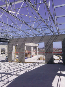
Figure 4. CFS roof trusses employed at the multi-use facility.
There is a paucity of guidance concerning the design, and test data documenting the response, of CFS roof trusses exposed to blast loading currently available to the structural design community. In particular, test data would be helpful in assessing the importance of the non-uniform and time-varying nature of roof blast loads on truss top chords and the stability bracing. Furthermore, test data could be used to formalize an analytical approach for CFS truss blast design by validating various modeling assumptions and providing response limits consistent with observed failure modes. Such testing could serve to promote the economical and consistent use of CFS trusses in DoD facilities.▪
Acknowledgment
The authors would like to thank Jon A. Schmidt, P.E., SECB, BSCP of Burns & McDonnell for his comprehensive review of the article and assistance in developing an equivalent static blast load expression that envelopes the shock response spectrum.