
Corrosion related damages are the root cause of numerous façade failures on masonry clad steel frame buildings (Figure 1). Corrosion of the underlying steel frame or anchorage can lead to cracking, spalling, displacement, and eventually the loss of entire masonry units or severe section loss of structural components. Corrosion is a quantifiable reaction, whereby initiation, propagation, and deterioration can be projected through comprehensive assessments and durability modelling.
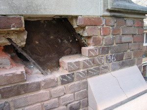
Figure 1. Cracking of masonry due to corrosion of the steel frame.
The ultimate reason for carrying out corrosion assessment work on existing steel frame buildings is to determine the long term behavior of the corrosion process that could cause damage to the historic façade. The end result of the testing and analysis is two-fold: to provide a predictive outcome from corrosion damages in the future and, where suitable, to determine if an electrochemical corrosion mitigation system such as impressed current cathodic protection (ICCP) is a viable corrosion mitigation option. This comprehensive approach to corrosion diagnostics and the use of ICCP has been used in historic steel-frame buildings since the early 1990s.
Corrosion Diagnostics
A corrosion assessment is one step towards understanding the root cause of deterioration and providing a maintenance, rehabilitation and repair plan (MR & R) that deals with service life. As the steel frame will impact the historic masonry it is embedded within, it is essential to understand the symbiotic relationship of the materials. Variations in masonry type, building envelope details, environmental parameters, and the performance of the overall building enclosure will impact conditions. The basis of investigations is to provide a service life model where the fundamentals are as follows:
1) Determination of mechanical and environmental loads (in laboratory tests and in service, real and simulated) to which materials or components are likely to be subjected,
2) Characterization (macro, micro, and surface) of materials and components,
3) Identification of degradation mechanisms of materials and components,
4) Determination of degradation kinetics of materials and components,
5) Identification and expression of performance requirements and performance criteria for materials and components, and
6) Organization and representation of computerized knowledge of materials and components.
The corrosion condition assessment employs various non-destructive and semi-destructive test methods analysed in conjunction with a thorough visual and physical inspection of the structure. Many of the tests were established to address concerns regarding corrosion of reinforcing steel in concrete.
In 1979, the first full scale trial of non-destructive testing was undertaken in England by the Department of Transport. As a greater understanding of corrosion related deterioration became established, the more comprehensive the testing procedures and condition analysis became. By 1990, service life predictions and determinations of the “maximum tolerable amount of corrosion corresponding to condition of failure” by the use of corrosion rates were being addressed.
During this time period, the notable effects of steel frame deterioration began having a visual and physical impact on landmark and listed buildings in the United Kingdom (UK). Historic Scotland funded a three year study which resulted in the publication of Technical Advice Notes (TAN) 20 Corrosion in Masonry Clad Early 20th Century Steel Framed Buildings. This study was the first large scale research initiative to introduce a corrosion condition methodology to the historic steel frame building. As such, the test methods, as applied to concrete, required a more refined approach when applied to the historical building stock.
The non-destructive approach as initially outlined in TAN 20, and subsequently refined by the National Association of Corrosion Engineers Task Group 460 (NACE TG 460), requires an understanding of corrosion pathology, knowledge of historic construction methods, construction details, and non-destructive test methods. Upon successful completion of a test program and inclusion of an ICCP feasibility trial, one can determine the most appropriate long term repair option for corrosion mitigation.
Applicable Test Methods
The test procedures utilized to determine corrosion conditions vary slightly from building to building depending upon the construction details, materials, location and exposure. A critical analysis of the results requires interpretation based on historic integrity as well as corrosion activity. What may be considered minor corrosion activity on an industrial concrete structure could be considered higher risk for a historic steel frame building or landmark concrete structure where there is a higher intrinsic and monetary value of the construction materials.
The mortar in-fill is essential for ensuring accurate test results and for the passage of the protective current to the steel member. This condition must be established prior to expending significant time on testing.
Previous and current repair details must be understood as they relate to corrosion, interpretation of test results, future repairs or adverse effects on electrically discontinuous steel from stray current for future repairs, and how the steel and electrolyte function together. The following test methods are key elements of the corrosion condition investigation for masonry clad historic steel frame buildings:
- Cover
- Resistivity
- Continuity
- Ecorr or Half Cell Potential
- Icorr or Corrosion Rate Testing
- Carbonation
- Chlorides (if applicable)
- Compressive Strength
- Knowledge of: previous repairs, masonry properties, and chemical make up steel geometry.
Whereby:
Cover provides protection to the steel from the elements and atmosphere.
Electrical continuity to the steel is required for corrosion testing and treatments, and must therefore be established in the investigative phases of work.
Resistivity is the ability of the electrolyte to pass current. Low resistivity values are conducive to, and have a direct correlation with, high corrosion rates (Icorr).
Ecorr or steel potential is established by the taking half-cell potential of the steel with a reference electrode (Figures 2 and 3).
Icorr or corrosion rates are measured by Linear Polarization Resistance. The resulting corrosion current and loss of electrons is equated to section loss based on Faraday’s Law of Metal Loss. This has a direct relationship with rust accumulation (Figures 2 and 3).
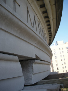
Figure 2. Electrochemical test area of masonry corresponding to Figure 3.
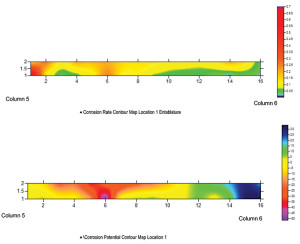
Figure 3. Contour maps of the test data of correlate probable corrosion risk (potential), high moisture, low oxygen and areas of active corrosion. Top contour corrosion rates, bottom contains half-cell potential.
Carbonation: the presence or depth of carbonation should be confirmed at the embedded steel. This can be carried out by laboratory analysis of mortar and infill samples, or in situ with pH reagents or indicators.
Chlorides do not usually pose a significant risk in steel frame buildings unless the building is located in a marine environment, or a sidewalk near the base of the building is subjected to de-icing salts in the winter.
Compressive strength of the electrolyte and cladding play an important role in understanding the durability of the material from the effects of corrosion. The higher the compressive strength of the cladding material, and the better the compactness of the infill around the frame, the sooner the masonry cladding will exhibit damages from the accumulation of corrosion scale.
As the various elements tested all possess a function in regard to the corrosion behaviour of the building, knowledge of the conditions and the interpretation of the data is required in the overall corrosion assessment (Figure 4, page 16). This information sets the basis of assessing service life of the structure and durability of the repair. Utilizing durability models, time to cracking and time to critical section loss can be determined to ensure the most appropriate repair is used.
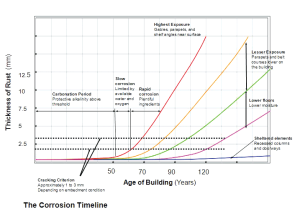
Figure 4. Corrosion timeline: These charts illustrate corrosion activity and deterioration of certain elements of the building within their service life.
Impressed Current Cathodic Protection
As a redox reaction, oxidation and reduction occur simultaneously in the corrosion reaction. The anodic reaction, or oxidation, is the loss of electrons. This causes the steel to revert to rust. The volume of the rust can be as great as ten times the amount of steel section loss. Simultaneous to this is the reduction reaction at the cathode site. The cathode reaction is harmless, and the cathode gains electrons that have been lost at the anode site. The electrons pass from the anode as ionic current through the masonry, moisture, or mortar electrolyte to the cathode site. The electrons return to the anode site as electrical current, creating a full circuit. This reaction is the basis of cathodic protection, whereby the corrosion cell is controlled, thus limiting damage to historic building fabric and providing a life extension to steel-frame structures.
The accumulation of corrosion scale damages the exterior masonry cladding where the tensile forces of the corrosion are greater than the masonry can withstand. Prior to large-scale losses and cracking, minor damages become apparent, such as hairline cracking and open joints.
For masonry clad buildings, Impressed Current Cathodic Protection (ICCP), which utilizes an external power source (versus a galvanic system), is the only suitable electrochemical technique to afford protection to the embedded steel. Impressed current systems are permanently embedded while galvanic systems are ephemeral in nature, based on the consumption rates of the metallic alloy consumed. For ICCP systems to be effective, the anodes are installed within the masonry and mortar back-up material, known as the electrolyte, and current is passed through the conductive medium. The anodes are never directly in contact with the steel or there will be a short circuit.
Cathodic Protection Materials
The requirements for an ICCP System for historic masonry construction include the following components:
Anodes
The most suitable anodes for ICCP in a historic steel frame building are discrete rod anodes. These are most often titanium with a mixed-metal oxide coating. Expanded mesh probe anodes with integral ballast resistors are particularly useful for insertion into the backup masonry at the fine jointing of stonework and the mortar joints of brick-work. Theses anodes are installed using a specialized cathodic-protection grout, which is then pointed over with traditional masonry pointing techniques. During installation, all anodes are installed and interconnected with a Titanium feeder wire. The anode wiring is then terminated at the positive terminal of the DC power supply unit.
As all exterior components are installed within the backup and never through the façade stone, the particular advantages of this system are:
- The anodes are not visible.
- Anodes can be installed using standard grouting and masonry pointing techniques at the time of external repairs.
- Anodes are usually situated parallel to beam and columns.
- There is minimal internal disturbance.
Cathodes
While anodes are installed to provide electrons to the steel, the areas of the steel frame targeted for treatment become the cathode. Wire connections to the steel frame provide a return path to the power supply unit, as the negative portion of the circuit.
Monitoring Cells
Reference electrodes which measure the steel potential are permanently embedded as part of the system. All systems require performance evaluations according to the National Association of Corrosion Engineers (NACE) and the British Standards European Norm (BSEN) standards.
Power Supplies
All external wiring is brought into the building and routed to the power supply units (PSU) or where most suitable for the structure. PSUs are generally placed on the interior of a building in a maintenance closet, drop-ceiling space, or basement.
PSUs or transformer rectifiers (T/Rs) utilized in steel-frame cathodic protection require finite control of current output and voltage limitation. The systems require so little current to polarize or protect the steel that there must be adequate control measures to ensure that over-protection and hydrogen embrittlement do not occur.
A schematic is provided in Figure 5, showing the layout of a system in a masonry-clad, steel-frame building. The rod anodes are attached to the [+] of the power supply (red), and the steel frame (cathode) is connected back to the [-] of the power supply.
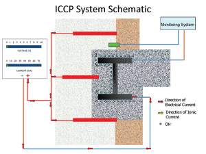
Figure 5. Cathodic protection schematic.
Track Record
The first cathodic protection (CP) system for the prevention of steel corrosion in a masonry structure was designed by Taywood Engineering Ltd. and completed in 1991. The CP system provided protection for the entrance colonnade of the Royal College of Science, Dublin. The entrance colonnade is a limestone structure containing two parallel structural I-beam members. Since its completion in 1991, regular remote monitoring via embedded reference electrodes has shown no corrosion problems. This has also been confirmed via annual visual inspections. Since the development of this first CP system for masonry, over 150 systems have been designed and installed for masonry buildings in the UK.
In the United States (US), the first full scale application was installed in 2004 to the façade of a prominent historic Chicago department store, which was built in multiple phases from the late 1800s to the early 1920s. Today, at least 20 of these systems exist in historic steel frame buildings in the US (Figure 6).

Figure 6. Completed system on steel frame buildings.
Conclusions
Since the 1990s, corrosion diagnostics and ICCP has been used on hundreds of heritage buildings. These systems have shown the possibility of protecting full-building façades from imminent corrosion related deterioration for listed and land-marked buildings. Where ICCP has been installed, it has been found to have a cost saving in excess of 50% in comparison with traditional repairs which require the removal of masonry, treating the steel, and reinstating or replacing masonry units. Additionally, the cost of ICCP is usually in the range of 10% of the overall exterior envelope repair scope.
The following conclusions can be made from the brief discussions presented:
- Steel-framed buildings constructed prior to 1940 are prone to corrosion related problems such as the cracking and displacement of masonry.
- Impressed current cathodic protection systems have been shown as an appropriate method of repair for the prevention of corrosion in early 20th Century steel-framed buildings.
- Cathodic protection systems for masonry-clad steel-framed buildings require a specialist’s knowledge of historical construction techniques.
- A corrosion survey with insitu trials is necessary prior to moving forward with a design.
- The overall investment in a long-term corrosion mitigation system provides economic incentive to a proactive approach.
- The loss of historic masonry and façade damage can be minimized with a proactive, long-term repair strategy.
- ICCP is specifically tailored to each building.
- ICCP adheres to preservation and conservation guidelines.
The design life of the systems range from 25 to 50 years; this is dictated by the power supply technology and internal wiring systems. While the design life of the anode and titanium wiring can exceed 50 years, based on the amount of current passed, the design life of the control systems will change as rapidly as technology allows.▪
References
G.J Frohnsdorff and J.W. Martin, Towards a Predictive Service Life. National Institute of Standards and Technologies.
J.Glanville, and Newman, J. “Performance Prediction of Concrete 1974–95.” Prediction of Concrete Durability: Proceedings of STATS 21st Anniversary Conference. London, England: E & F Spon. 1992: 9
NACE TG 460 is currently developing a State of the Art Report for Testing and Evaluation of Corrosion on Steel Frame Buildings, and is an extension of the work carried out by Task Group 329. TG 329 issued a State of Art Report for Corrosion Mitigation of Historic Steel Frame Structures.
For a general condition survey, as applicable to concrete, The Concrete Society and the American Concrete Institute (ACI) have established manuals for investigations. For the historic building community, engineer Donald Friedman and architect Martin Weaver have written extensively on inspections, investigations, conditions, and materials to provide seminal texts in this field. Peter A.J. Gibbs’ publication TAN 20 is the first book to address corrosion engineering in the context of historic buildings.