
Reducing Building Floor-to-Floor Height
At the early stage of building design, most architectural designers start with functional block schematic floor plans and the structural floor system. The selection of the floor system is one of the most important considerations in building design. Each alternative demands a certain depth, which results in different building floor-to-floor heights. Lowering this depth allows the amount of materials used – such as exterior cladding, interior walls, partitions, stairs and other non-structural components – to be reduced. In high-rise building construction, it allows extra floors to be added within the proposed building height. On expansion projects, it helps facilitate the need to match existing floor elevations.
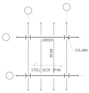
Figure 1.
Non-Prismatic and Simply Supported Girder
In conventional composite steel-concrete floor construction, the beam and girder cross-sections are uniform throughout the length of the members; i.e., they are prismatic members. Figure 1 shows a typical floor framing plan with simply supported beams and girders, which are required to have the maximum moment capacity at mid-span; the required moment capacity near the supports can be much less. This article suggests that making the girder non-prismatic, by reducing its depth near the support to match the beam depth, will provide additional space to accommodate the largest mechanical ducts, thus reducing building floor-to-floor height (Figure 2). It should be noted that only the girders that are above and perpendicular to the ducts need to have their depth reduced; therefore, the number of girders to be modified can be kept to a minimum.
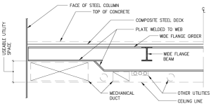
Figure 2
The procedure for designing the girder may be summarized as follows:
- Design the girder as a conventional composite member; i.e., select a wide flange steel section and determine the required number of shear studs.
- With the length of the reduced section required for the largest mechanical duct, find the bending moment at the start of the reduced section.
- Design the reduced section by selecting the bottom flange plate required; the depth of the reduced section should match the typical depth of the beams.
- Check the vertical shear capacity.
- Check the horizontal shear strength of the concrete slab and provide reinforcement as required. Note that such reinforcement is usually required for thin slabs. The amount of reinforcement also depends on the percentage of composite action (number of shear studs); the higher the percentage, the more reinforcement is required.
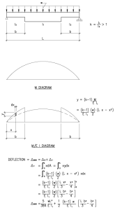
Figure 3.
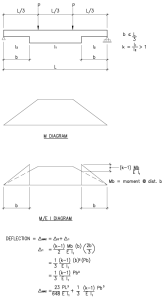
Figure 4.
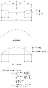
Figure 5.
Serviceability Requirements
The deflection formulae for non-prismatic members (reduced depth at both ends) subjected to uniform load and concentrated loads have been derived and shown in Figures 3, 4 and 5 respectively. Notation is defined as follows:
I1 = Larger moment of inertia at center portion of the beam/girder
I2 = Smaller moment of inertia at both ends of the beam/girder
k = I1 / I2 > 1
b = Distance from support to the point where stiffness changes from I1 to I2
w = Uniform load; P = Point load; L = Span length; E = Modulus of Elasticity
In the design example, the girder effective moment of inertia (Ieff) at the full and reduced sections will be determined and used in calculating the maximum deflection.
Section L5 of the AISC Specification for Structural Steel Buildings (ANSI/AISC 360-10) requires that “the effect of vibration on the comfort of the occupants and the function of the structure shall be considered. The sources of vibration to be considered include pedestrian loading, vibrating machinery and others identified for the structure.” As in any floor system design, the vibration characteristics of the floor system – i.e., the natural frequencies and the amplitude/acceleration due to certain appropriate dynamic loading – must be evaluated and satisfied. Refer to AISC Steel Design Guide #11, Floor Vibrations Due to Human Activity, for further information and the design procedure.
Team Coordination
Design team coordination is essential, particularly between the architect and the mechanical and structural engineers. The layout of large mechanical ducts and other utilities must be defined on plans and sections in order to eliminate conflicts, and to take full advantage of the additional space created. It should be noted that the largest supply air duct originates from the mechanical vertical chase and, run horizontally, can usually be reduced in size along its length. This, in turn, may eliminate the need to reduce the girder depth near the end of the duct.
Design Example
Design a typical interior composite girder for an office floor with a bay size of 30 feet × 30 feet and live load of 80 psf throughout for the flexibility of future corridor arrangements. The girder depth must be reduced to match the beam depth at one end (or both ends as required), the shallower depth beginning at a distance of 6 feet from the column centerline (Figure 6). The governing code is the 2012 International Building Code (IBC). Assume shored construction to minimize the design calculation.
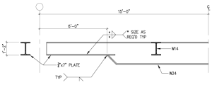
Figure 6.
Given: Floor framing as shown in Figure 1, with column line dimensions of 30 feet × 30 feet. Concrete: 3.5 inches, 120 pcf lightweight concrete, f´c = 4 ksi. Composite steel deck: 20-gage, 2-inch deep. Structural steel: Fy = 50 ksi. Live load = 80 psf, partition load = 15 psf, MEP = 5 psf, miscellaneous allowance = 5 psf. Concrete and steel deck weight = 47 psf; total dead load = 47 + 5 + 5 = 57 psf. With reduction per IBC Section 1607.10.1, live load = (80 + 15) [0.25 + 15 / (2 × 10 × 30)1/2] = 82 psf. W14×30 with (33) ¾-inch diameter shear studs will satisfy the design loads.
Design of composite girder: Assumed weight = 60 plf, dead load = (57 × 10 + 30) × 30 = 18,000 pounds, live Load = 82 × 10 × 30 = 24,600 pounds. Reactions: RDL = 18.0 + (0.060) (30 / 2) = 18.9 kips, RLL = 24.6 kips, RTL = 18.9 + 24.6 = 43.5 kips. Moments: MDL = 18.0 (10) + (0.060) (30)2 / 8 = 186.7 kip-ft, MLL = 24.6 (10) = 246.0 kip-ft, MTL = 186.7 + 246.0 = 432.7 kip-ft. Try W24×55, calculate composite section properties: b = L/4 = 30 × 12 / 4 = 90 in, n = Es / Ec = 11, Actr = b × t0 / n = 90 × 3.50 / 11 = 28.64 in2, yb = [28.64 (23.6 + 2 + 1.75) + 16.3 (23.6) / 2] / (28.64 + 16.3) = 21.71 in, Itr = 3,891 in4, Str = 3,891 / 21.71 = 179.2 in3, St = 3,891 / (23.6 + 2 + 3.5 – 21.71) = 526.5 in3, Vh = 0.85 × 4 × 3.5 × 90 / 2 = 535.5 kips or Vh = 50 × 16.3 / 2 = 407.5 kips, Seff = 432.7 × 12 / (0.66 × 50) = 157.3 in3, Vh´ = [(157.3 – 114) / (179.2 – 114)]2 × 407.5 = 176.9 kips > 0.25 (407.5) = 101.9 kips (OK), Ieff = 1,350 + (176.9 / 407.5)1/2 (3,891 – 1,350) = 3,024 in4. Allowable horizontal shear, q = 13.3 × 0.88 = 11.7 kips. Number of shear studs required for half span = 176.9 / 11.7 = 15.1, minimum required = 2 × 16 = 32 total.
Moment at reduced section: At 6 feet from column center line, MbDL = 112.3 kip-ft, MbLL = 147.6 kip-ft, MbTL = 259.9 kip-ft. At the reduced section, the steel girder depth is 14 inches; try ¾ inch × 7 inches bottom flange plate to match the W24 flange width. Determine the composite section properties in similar fashion as before: Ix = 452 in4, Sx = 75.1 in3, As = 13.85 in2. For composite section: Yb = 13.93 inches, Itr = 1,771 in4, Str = 1,771 / 13.93 = 127.1 in3, Vh = 50 × 13.85 / 2 = 346.2 kips, Seff = 346.2 × 12 / (0.66 × 50) = 94.5 in3, Vh´ = [(94.5 – 75.1) / (127.1 – 75.1)]2 × 346.2 = 48.2 kips < 0.25 × 346.2 = 86.6 kips, Ieff = 452 + (86.6 / 346.2)1/2 (1,771 – 452) = 1,112 in4. Number of shear studs required = 86.6 / 11.7 = 7.4; these studs are to be placed over 6 feet length, therefore the number of studs over half span should be 7.4 × 15 / 6 = 18.5 studs; use 19 studs (38 total).
Vertical Shear: fv = 43.5 / (0.40 × 13.25) = 8.21 ksi < 0.4 Fy = 20 ksi (OK).
Horizontal Shear: Check concrete slab reinforcement transverse to the girder span. At girder centerline, horizontal shear capacity provided = (19 × 11.7) / 15 = 14.8 kips/ft. Therefore, at a distance of 4 inches from the girder centerline where concrete slab thickness is 3.50 inches, the shear stress v1 = [14.82 / 2 (12 × 3.5)] × (45 – 4) / (45) = 0.161 ksi, v1u = 1.44 × 161 = 232 psi (combined load factor = 1.44). From ACI 318-11 section 11.6 and Vn = 0.8Avffy + AcK1, Avf = 0.095 in2, so use #3@12 inches. Note that AISC 360-10 Commentary section I3.2.1 recommends minimum reinforcing area = 0.002 × 3.5 × 12 = 0.084 in2.
Deflections: From Figure 4, k = I1 / I2 = 3,024 / 1,112 = 2.72. ∆LL = 23 (24.6) (30 × 12)3 / 648 (29,000 × 3,024) + 24.6 (2.72 – 1) (6 × 12)3 / 3 (29,000 × 3,024) = 0.46 + 0.06 = 0.52 inch < L / 360 = 1.00 inch (OK). Using the deflection formulae shown in Figures 3 and 4, ∆TL < L / 240 (OK).
Conclusion
The above design example demonstrates that by reducing the depth of the girder near its support, and with proper coordination among the design team members, the building floor-to-floor height can be reduced. The increase in girder deflection is very small, and therefore, the effect on the floor vibration is minimized. The additional cost of the girder fabrication is likely to be less than the savings in cost on the exterior wall and various interior constructions.▪
Acknowledgements
The author would like to thank Malee Kaolawanich, P.E. at the Building Mechanical System Branch, Office of Research Facilities, National Institutes of Health, Bethesda, Maryland, who reviewed the article as it relates to the space required for the HVAC system. He would also like to thank Mike Rosenberger at Cates Engineering, Gainesville, Virginia, for his effort in drawing the figures.