
First Major Iron Cantilever Bridge in the United States
When engineers think of cantilever bridges, the Quebec Bridge with its 1,800-foot span and the Firth of Forth Bridge with its 1,710-foot spans come to mind. The cantilever principle in metal originated in Europe and the United States, but examples of cantilevers in wood and stone were found in many countries in the Far East, such as India, Tibet, China and Japan, as well as Norway and South America. The best known are Shogun’s Bridge in Nikko, Japan and the Wandipore Bridge in Tibet, both built in the mid 17th century. Lewis Wernwag built small cantilevers in wood and iron across Frankfort and Neshaminy Creeks outside Philadelphia around 1812 that he called “Economy Bridges.” Albert Cottrell patented and built several cantilevers similar to the Wandipore Bridge in New England between 1840-1860, calling them “Solid Lever Bridges.” It wasn’t until Heinrich Gerber built his cantilever in iron across the Main River at Hassfurt, Germany in 1866 that the merits of the cantilever system in iron began to be appreciated.
John Fowler and Benjamin Baker illustrated the principle of the cantilever bridge in 1887 to indicate how the Firth of Forth Bridge was designed. Working from the left is the anchorage, the anchor span, a tower, a cantilever arm, a suspended span, a tower and another anchor span and anchorage. The arms of the two tower men are in tension with the struts up from their chairs in compression. The counterweights (anchorages) at the ends balance the suspended and cantilever arms. Before this illustration was published, a competition in the 1870s was held for a bridge to span the East River in New York City across Blackwell’s Island. Several men proposed iron cantilevers, including William Petit Trowbridge who originally proposed one in 1868 and again in the 1870s competition. Henry Flad, Charles Macdonald and others submitted designs, but no action was taken.
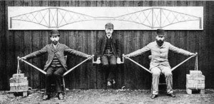
Firth of Forth cantilever illustration.
In 1851, the Lexington & Danville Railroad, with Julius Adams as Chief Engineer, retained John A. Roebling to build a railroad suspension bridge across the Kentucky River for a line connecting Lexington and Danville, Kentucky. It was clear to Adams that a bridge across this gorge would be the most difficult part of building the 33-mile long railroad. The longest iron truss spans for railroads in the early 1850s were built by Squire Whipple, 147 feet on the Albany Northern Railroad, and by Albert Fink, who built a three span, Fink Truss, each of 205 feet, across the Monongahela River for the B&O. It was also obvious to Adams that, with the turbulent nature of the river and the great depth of the gorge, the required false work for a truss bridge would not be possible at this site. The site selected for the bridge was just west of the intersection of the Dix and Kentucky Rivers. The gorge was described as,
The Kentucky River…flows between two walls of limestone rock from 300 to 450 feet high-almost perfectly vertical, and varying from 1,000 to 1,300 feet apart. This canyon is extremely tortuous, and the stream flowing through it is about 300 feet in width at ordinary stages. The maximum rise above low water is 57 feet, and the extreme flood speed observed was eight miles per hour.
After building the towers, anchorages and with wire to spin the cables on site, the company ran out of money in 1855. It wasn’t until 1873 that the Cincinnati Southern Railroad solicited proposals to build a bridge at the same site. C. Shaler Smith, and the Baltimore Bridge Company (STRUCTURE, April 2008) in the first competition, submitted a plan for a five span continuous truss bridge with three river piers in which they assumed points of contraflexure for calculation purposes. The problem with continuous trusses was the danger of unequal settlement of the piers and that temperature changes could place large stresses on the bridge members. In addition, it was difficult to purchase iron with a constant modulus of elasticity that was necessary to make the required calculations. Flad & Pfeiffer, a firm from St. Louis, submitted a plan for a continuous girder bridge with the chords cut following the plan adopted by Gerber. In the second round of submittals, a number of meritorious plans were presented; the one finally accepted was that prepared by Smith for a cantilever bridge, erected as a continuous truss, in wrought iron erected by a new and novel method using Roebling’s towers as anchors.
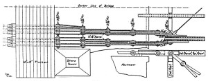
Smith erection detail for cantilever span using Roebling’s towers and anchor chains.
Thomas Lovett, the Chief Engineer for the Cincinnati Southern, decided that there should only be two piers on the banks of the river, 375 feet apart and set 375 feet from the abutments. Smith chose to utilize Whipple Double Intersection Trusses and to run the trains on the top chords of the trusses.
Smith cantilevered the first 196 feet 10 inches of his trusses out from the abutments to temporary wooden piers. This was unlike Eads who, at St. Louis, had built temporary wooden towers on the tops of his piers and extended iron bars from the top of the towers down to the deck to support cantilevered arch segments until they met at mid span. Given the height of the piers and length of span, Smith could not use this process. He chose to place a heavy beam built up of 12-inch x 12-inch oak timbers, in 11 rows and 11 columns, approximately 40 feet long, across the backs of Roebling’s columns. He then drilled six holes on each side through the timber on the line on each truss and inserted 4-inch diameter bolts with one end threaded and the other end with a forged eye. He then connected the bolts to a series of eight 7-inch x 1-1/4-inch anchor chains salvaged from Roebling’s anchorages. Using the links, he extended a chain to a connection at the end of the top chord of the trusses. In order to have the cantilever arrive at the proper elevation when it reached the temporary piers, he simply adjusted the nuts at the ends of the bars, and used jacks, braced against the abutment rock, to push against, or relax, the ends of the lower chord. After the trusses reached the temporary pier, they were adjusted for elevation with jacks and then extended to a permanent iron pier 375 feet off the abutment.
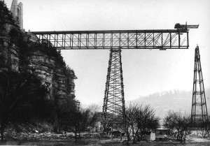
Erection progress showing temporary wood pier and permanent iron pier. Note extra erections diagonals to right of temporary pier.
From that point, they were cantilevered another 187½ feet to mid span of the river span. The erection process, the temporary wooden pier was then reused and moved to the opposite shore and the process repeated until the trusses met at mid span. What Smith did can best be told by a contemporary account that appeared in The Railroad Gazette of January 19, 1877, written while the bridge was under construction. It said in part,
The viaduct as now being constructed consists of three spans of 375 feet each, resting on the bluffs and on two iron piers, which latter in turn are supported by stone piers, each 120 feet long by 42 feet in width at the base. The iron piers consist of four legs each, and while having a base of 71 feet 6 inches by 28 feet, their longitudinal profile terminates in a point at the top, or rather in a 12-inch pin upon which the truss rests as on a rocker. The entire pier is a complete structure within itself and can be rolled about on the masonry, the pedestal resting on double roller beds for this purpose.
The truss itself is, during erection, a continuous girder of the Whipple type; but after erection it will be converted into one continuous girder 525 feet long, projecting at each end 75 feet over its points of support, and carrying from each of these cantilevers a 300-foot span, which bridges the distance from the end of the cantilever to the bluff. It was necessary to make the bridge a continuous girder in order to raise it without false-work; and the hinges were obligatory because the rise and fall of the pier from thermal changes will amount to fully two inches, and would vary the strains hourly in a true continuous truss. The truss is 37.5 feet deep and 18 feet wide, and each bay is divided into 20 panels of 18.75 feet each. All connections between ties, posts and chords are hinged on pin connections but the chords are riveted to each other throughout, with the novel addition that the pin carrying the tie bars is forced into the chord splice by hydraulic pressure, and thus does duty as a rivet.
After the bridge seat was cut out of the cliff, the end posts were set up and the first section of bottom chord laid in place, each chord being continued back to the rock by a large screw jack placed between its rear end and the face of the bluff. Then the top of each end post was bolted back to Roebling’s towers by anchor bolts, which has a screw adjustment…
It will readily be seen that with these connections once made the structure could be built out panel by panel until the limit of strength of the anchorage bolts or of the top chord or the available resistance of the Roebling towers had been reached. This last was the governing factor, and the other parts were proportioned to suit accordingly…
The next flight was to the permanent pier, 178 feet 2 inches. When the span left the bluff the iron pier was started upward from the masonry, and the two met in mid-air, the working force of each arriving at the point of junction within two hours of each other. The weather was cold and the span short, owing to the compression of the lower chord and the effect of temperature; but this had been foreseen, and the huge pier weighing 400,000 lbs. was moved on its rollers toward the span until the pier that connects the two could be put in place. This done the truss was built out as before until the middle of the river was reached…
The last operation will consist in taking out the bottom chord pins in the fourth panel north and south of each pier in arbitrarily and without ambiguity the strain in all parts of the truss in order that there may be no double action at the hinging points, both web systems are concentrated into one in the two panels adjoining the point at which the chord is cut [note this article was written before the bridge was completed]…
Altogether, in the novelties introduced in both construction and erection, and in strict adherence to theory throughout, this great viaduct-the most important in the world in regard to length of span in connection with its height-is probably unsurpassed by any similar work now existing.
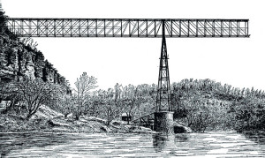
Bridge erected to mid-span awaiting erection from opposite shore. Note extra diagonals removed when temporary pier was removed.
Once the span left the temporary wooden tower’s additional diagonals, with inclinations towards the permanent iron pier were placed as “the diagonal tension members of the trusses slope toward the abutment, and consequently give no support for erection purposes. To erect this section of the trusses, use was therefore made of false diagonals. These were 4 x 7/8-inch iron bars, with end pinholes, and were slipped over the pins outside of the permanent diagonals. Two bars were used on each side of the chords, the pins being extended to provide for their use.” Once the permanent pier was reached, these bars and the temporary wooden piers were removed and moved to the opposite shore and reused. As is the case in any bridge erected by cantilever methods, the truss members had to be sized to handle erection loads, dead plus traveler, as well as operational live and dead loads.
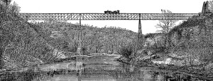
Bridge complete with locomotive and Roebling towers.
The official load test on the bridge was conducted on April 20, 1877, with the greatest deflection less than two inches. It was not formally dedicated until September 17, 1879, when President Rutherford B. Hayes and General William T. Sherman were in attendance. The Railroad Gazette finished its coverage of the bridge by stating, “the whole work was carried out very successfully, and reflects great credit upon the engineer, Mr. C. Shaler Smith, who designed the work, and the Baltimore Bridge Company, which executed it.” The bridge cost $404,373.31 and used 3,654,280 pounds of iron. It was estimated that an additional 40,000 pounds of iron was required as the result of building the bridge by the cantilever method.
What Smith had done, with the assistance of the Edgemoor Iron Company of Wilmington, Delaware, was to develop an entirely unique design and construction technique, and to implement this “novelty” in bridge building over a river that was 275 feet below. In addition, he built the entire iron superstructure in four months and four days in the middle of a Kentucky winter. The Railroad Gazette wrote the bridge parts went together, “like a Springfield musket.”
Smith went on to build major cantilevers over the Mississippi and St. Lawrence Rivers. The first cantilever to use a central suspended span was by C. C. Schneider across the Niagara River in 1883. In 1911, Gustav Lindenthal built a steel bridge around Smith’s bridge at a higher level that still serves.▪
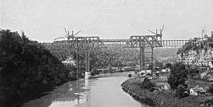
Lindenthal’s Bridge being built around Smith’s 1911.