
Integrating 3 Ds in 3D is Key to Project Success
Integrating 3D modeling software programs for the three “Ds” for this project – Ram for design, Revit for drafting and Tekla for detailing – proved to be the key for success for this fast track design-build project at a major Marine Corps base in California.
The project consists of three adjoining structures, with very diverse functions, which form the new 131,000 square-foot Center for Naval Aviation Technical Training Complex (CNATT). The primary function of the complex is to house all aviation mechanics involved with the maintenance and repair of Huey and Cobra helicopters at the Marine Corps base at Camp Pendleton. This includes administrative activities, training, and the actual maintenance and repair of the helicopters in an open-bay hangar area.
Aesthetically, one structure, rather than three, would have served the purpose. However, due to the diverse programming needs of each activity and structural system incompatibility, the team decided it was necessary to design three buildings so there could be seismic separations between them. The tall hangar building with a braced frame lateral load resisting system is one building (Figure 1); the four-story administration building with masonry shear walls is the second building; and a three-story classroom masonry shear wall building with an open space and column-free auditorium on the first floor is the third building. The team individually modeled and analyzed each building separately to manage the electronic file sizes. This also allowed several individuals to work on the same model at the same time through the work-sharing feature of Revit.
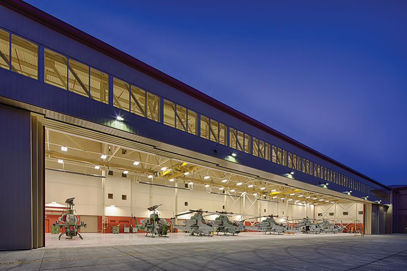
Figure 1. CNATT Helicopter Maintenance Hangar at night.
The need to quickly double the size of its helicopter maintenance and repair training facilities was “mission critical” for the Marines in order to meet the rapidly growing demand for Huey and Cobra helicopters used in global combat operations. Therefore, the Marine Corps put the project on a fast track schedule and selected design-build as the method of project delivery. The Corps also wanted the project to be a showcase design to reflect the vision of CNATT as “the preeminent leader in aviation maintenance training.”
These goals presented significant challenges to the designers and builders. The accelerated schedule meant the team needed to start work immediately based on the parameters of the project outlined in the Request for Proposals (RFP). Another critical challenge was figuring out how to shorten the length of time required to fabricate a 320-foot span truss for the hangar building so the entire project could be designed and built within the allotted time frame. It also meant the design-build team had to resolve several potential problems during the planning and design phases of the project rather than address them later during the construction phase, as is normally the case. For instance, the team needed to overcome the problem of limited site access so that several heavy-duty cranes could be positioned to lift the hangar door truss. Another important issue to resolve involved the sequencing of field-assembled members for storage and erection.
Use of BIM
The team relied on 3D Building Information Modeling (BIM) software to help speed up the design timeframe and improve the quality control process. In order to achieve these goals, the team developed the following system. First, the engineers used the architectural Revit model to add structural members without any particular attention paid to the sizing of the members. The second step required them to export the Revit model to RAM/Risa for structural member sizing. Once they finished this task, the engineers then brought the analyzed model back to Revit for preparation of construction documents before finally exporting the documents to Tekla for steel detailing.
During the initial phase of the project, the structural team proposed a system of open web steel joists for the framing of the hangar roof system. As the work progressed, they realized they needed larger openings for the mechanical, electrical, and plumbing (MEP) lines to pass through the truss web members in the hangar building. This changed the direction of the hangar roof framing system from an open web steel joist type of truss to a custom-designed roof truss with fewer webbing members.
Using Revit to model the actual truss member sizes and Tekla for the connection plates for the hangar roof truss connections allowed for detailed coordination among all the disciplines. Similarly, by modeling all of the masonry wall, roof, and floor-framing members in the administration and classroom buildings, it was possible to coordinate the exact location of MEP penetrations through the shear walls to avoid conflicts during construction. To facilitate this process, the team held weekly BIM coordination meetings among all the stakeholders, including the steel fabricator, to expedite the critical decision-making on the changes needed during the design work schedule. These meetings and coordination efforts saved money by avoiding conflicts between the various systems during construction.
The result was the development of “No-Fly Zones” which are designated areas that are off-limits for contractors to position their pipes, duct, or other penetrations in the masonry shear walls in the administration and classroom buildings. Basically, the “No-Fly Zones” ensured that the inadvertent placement of unwanted holes or penetrations in critical sections of the walls would not affect the major components of the wall such as the chord bars, control joints, and beam pockets.
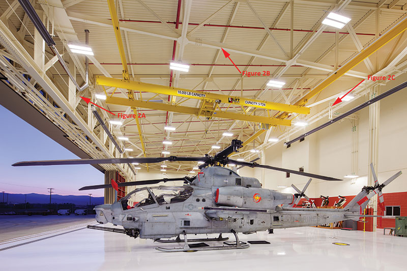
Figure 2. Helicopter Maintenance Hangar.
Design Challenges
Hangar
The anchor feature of the aviation training complex is a high-bay hangar space to house nine helicopters. The basic structural system design for the hangar portion of the building includes a corrugated metal roof deck spanning between steel purlins (Figure 2). Monoslope custom steel trusses (transverse trusses), spaced at 25-foot intervals, support the steel purlins (Figure 2b). A three-dimensional space truss at the front of the hangar, coupled with lattice-type “box” columns, support the header truss along the front of the hangar (Figure 2a). The 3D space truss, which is 10 feet wide and 16 feet deep, spans 320 feet along the front of the hangar, providing a clear, unobstructed entry for normal operations of helicopters. A single truss supported by individual columns provides support at the rear of the hangar (Figure 2c). The transverse trusses cantilever out 12 feet on the rear side of the hangar to reach the outline of the adjoining administration building and to provide enclosure between the two buildings. Masonry exterior walls enclose the hangar door pockets. A system of horizontal trusses in the plane of the bottom chord of the transverse trusses provides diaphragm action for distribution of lateral loads to the supporting brace frames. Two independent, 5-ton bridge cranes covering the entire hangar bay provide weight handling in the operation of the facility. Rail attachments to the bottom chord of the transverse trusses support these cranes.
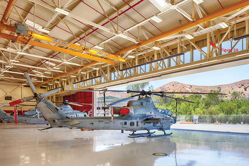
Figure 2a. Box truss.
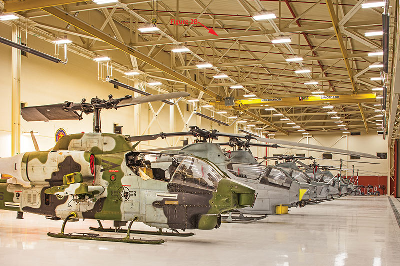
Figure 2b. Transverse truss.

Figure 2c. Single-ply truss.
The hangar space required clear, unobstructed entry to allow for the normal operations of the helicopters. In order to accommodate a 29-foot clear hook height in the hangar bay, the structural engineers had to evaluate the ”box” truss for various shapes and sizes to minimize the tonnage. This was particularly challenging because they were dealing with very limited depth available for the “box” truss at the front of the hangar. The designers also analyzed the transverse trusses supporting the bridge crane rails, resulting in the addition of strategic strengthening members within the truss to limit the deflection to L/600 for proper operation of the crane rollers. The final design was a 320 foot-long span “box” truss with a weight of 250 tons.
Administration Building
Adjacent to the hangar building is a four-story reinforced concrete masonry administration building which forms one leg of the “L”-shaped structure. This building has a composite floor system, interior steel columns, and exterior bearing reinforced masonry shear walls. The second-floor elevation is 16 feet and the subsequent floor-to-floor height is set at 14 feet. The biggest challenge for the design team for this building was to get natural lighting into the upper-level classrooms in order to meet the LEED natural day lighting requirements. This meant the team had to design the roof of the hangar and the height of the administration building in such a way as to allow for natural light to penetrate the upper-level classrooms.
Classroom Building
The classroom building, called The Applied Instructional Facility (AIF), forms the other leg of the “L” shaped building. It is separated from both the hangar and the administration building. The AIF building includes electronic classrooms for up to 400 students, aviation training shop laboratories, and a column-free auditorium at the first floor with a seating capacity of 250.
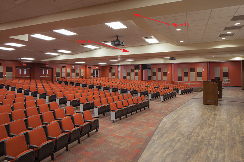
Figure 3. Column-free, multi-purpose auditorium.
Interior steel columns and the exterior masonry walls form the support of the structure at the upper levels. The interior steel columns and the exterior masonry walls terminate at the second floor to allow for a large column-free multi-purpose auditorium (Figure 3). In order to transfer loads, the engineers designed an 8-foot deep concrete transfer girder spanning 80 feet for the support of the 3-story exterior masonry wall above the auditorium (Figure 3b) and a 5-foot deep tapered steel girder to support the upper level interior steel columns (Figure 3a). The designers limited the deflection of the concrete and steel girders to L/600 to avoid cracking in the masonry walls and excessive defection in the steel girder. Holes in the 5-foot deep tapered steel girder accommodated passage of the utilities from one side of the auditorium to the other.
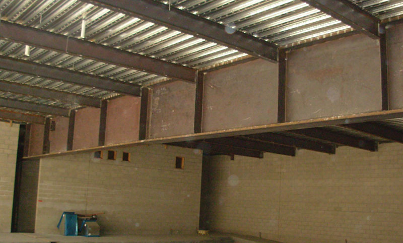
Figure 3a. Construction photo inset of 5-foot deep tapered steel girder.
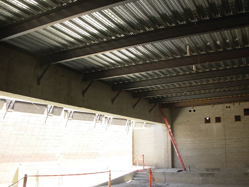
Figure 3b. Construction photo inset of 8-foot deep concrete transfer girder.
Steel Fabrication and Construction
The designers, contractors, and fabricators needed to make an important decision about the means and methods of construction because they were dealing with two difficult field issues. The first challenge involved access to the site, which was very limited. The second challenge involved the difficulty of positioning the cranes required to lift the main entry “box” truss of the hangar. In the end, the team decided it was more desirable to field-bolt the box truss rather than shop-weld it, because field-bolting would provide more flexibility for fabrication of smaller pieces and assembly in the field.
To achieve some level of economy, the smaller transverse trusses were fabricated into two pieces in the shop and field assembled into a single truss in the field, and then lifted into position as a single piece one-by-one using a single 200-ton crane (Figure 4). For the box truss, the fabricator shop-welded connections for the top and bottom “ladder” chords into five segments. These chord segments, as well as all the webbing members, were field-bolted for the entire truss assembly to be put together and lifted into position using two 200-ton cranes. The decision to design and build the entire truss on site enabled the team to trim nearly 12 weeks from the original design/construction schedule.
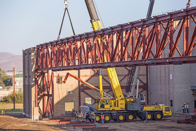
Figure 4. Field-fabricated truss for hangar.
Conclusion
The design and construction process is constantly evolving. 3D modeling available through BIM has only been around for a few years. In a few more years, designers and builders most likely will simultaneously access cloud-based information in real time. At this point in time, however, the most valuable lesson learned by this structural engineering team is a time-honored, practical lesson. And that is, the best way to avoid any field coordination problems during construction is to identify and deal with critical design and construction issues immediately at project start.▪
Photos by Pablo Mason, courtesy of Harper Construction.