
After 30 Years, a Friary Project continues to Provide Valuable Lessons
In 1981, a young architect and the author were tasked with designing a friary at Siena College in upstate New York. The friary is a residence for the Franciscan Friars who are administrators, professors and staff members at the college. The building (Figure 1) includes two residential wings and a large entrance and common area. Structurally, the residential wings use cold-formed metal framing as bearing and shear walls with bar joists and metal roof deck framing to create a gable shape. The wings are one-story with double loaded corridors; one wing has a partial basement. The common area has two stories framed in structural steel framing and bar joists. The lower level aligns with the partial basement of one wing.
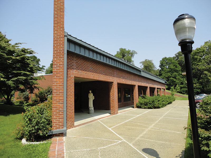
Figure 1. East entrance into common area (2014).
The architect’s conceptual design included a cavity wall with exterior brick veneer and interior brick veneer. The design team discussed options for emphasizing the masonry, since one of his design goals was to disguise the cold-formed metal and steel framing. This led to the use of brick beams throughout the building so that there would be no exposed steel framing over the openings. The more conventional approach would use exposed steel plates and angles above the openings, but they would not provide the aesthetic desired.
This article is a look back at the design and construction of over 50 brick beams that became an architectural highlight of the building. These brick beams were built with simple construction techniques that are as valid today as they were in the 1980s. A key point here is that elegant and sophisticated masonry buildings need not be complicated to design or construct.
Types of Brick Beams
Three types of brick beams were developed for the building. In each case, the beams fulfilled a structural and an aesthetic purpose. One type was an interior beam that crossed the corridors of the residence wings. The second was an interior beam used in conjunction with steel framing. The third was an exterior beam used in conjunction with steel framing and the exterior cavity wall.
Interior Brick Beam
This beam type was the simplest of all three to construct (Figure 2). The three-wythe beam supports its self-weight and a knee wall of cold-formed metal framing that is above the ceiling. There are two of these beams at intervals along the corridors at entries to the residence rooms.
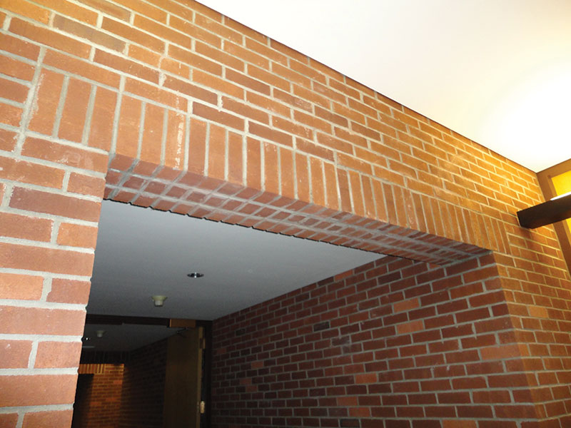
Figure 2. Interior brick beam.
The flexural reinforcement for the beam is placed in a grouted core (Figure 3a). The depth did not require shear reinforcement; the #2 stirrups are used to position the flexural reinforcement. Figure 3b shows a cross-section when wider beams are needed.
The formwork was simply bottom forms of plywood sheathing on 2 x wood joists spanning across the corridor (Figure 3a). The brick beam was constructed on the sheathing. Once the masonry design strength was reached, the formwork was removed and the bottom mortar joints were raked out and pointed with fresh mortar to provide a finished appearance.
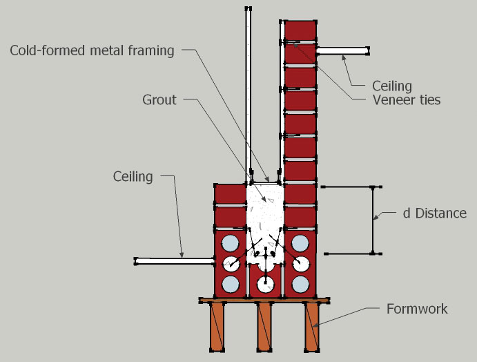
Figure 3a. Three-wythe interior brick beam.
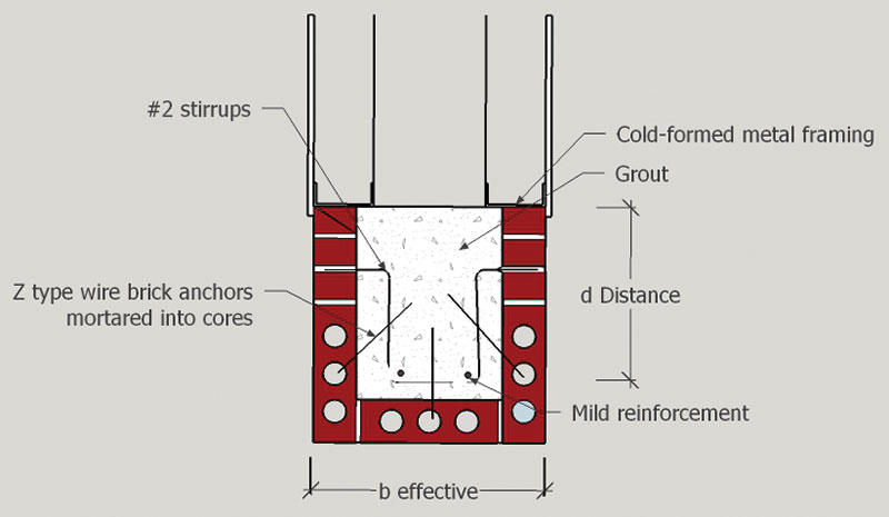
Figure 3b. Wide interior brick beam.
The design methodology in 1981 used allowable stress design (ASD) procedures. While still applicable today, the current code (TMS 402, Building Code Requirements for Masonry Structures) now allows Strength Design to be used as well. There are many publications (such as the Masonry Designers Guide from The Masonry Society) that illustrate the design steps using either ASD or Strength. The reinforced masonry beam carries all the dead load of its self-weight and the superimposed loads from above.
For this project, all of the beams were site-built. Today, prefabricating these beams and setting them in place to speed up construction could also be considered. Movement joints at each are necessary unless the supporting walls are short, as in this project.
Interior Brick Beam with Steel Framing
Many of the large openings required structural steel for the primary framing. However, the desire was still to have exposed brick beams (Figure 4).
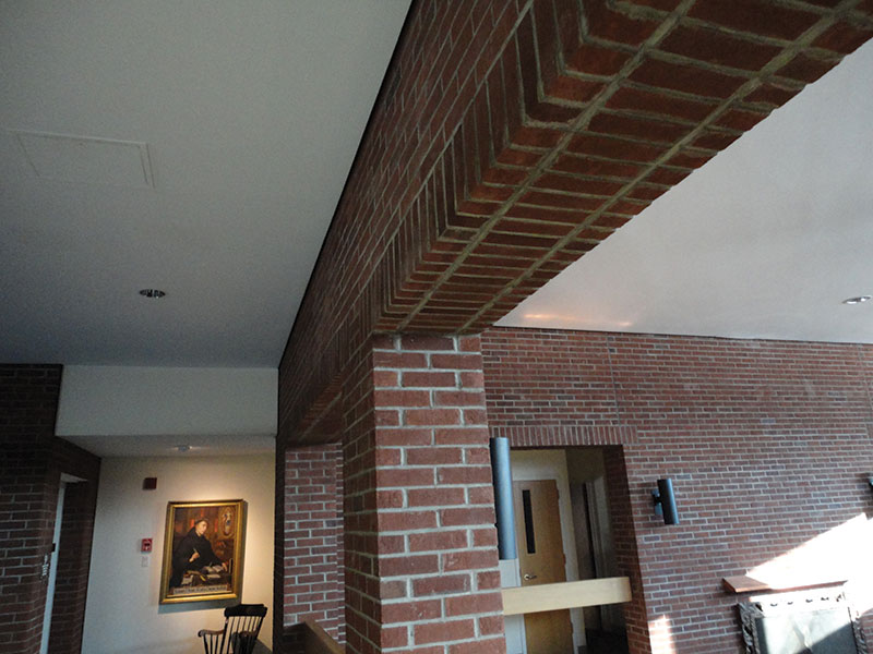
Figure 4. Interior openings with masonry beams.
In Figure 5, there are encased steel columns and steel beams. The steel framing was used for the floor and roof framing since there was insufficient depth available for brick beams alone to support the loads. The steel beams support roof dead loads, self-weight of the framing and the walls above; floor beams carry floor dead loads. Superimposed dead and live loads are distributed to both the steel framing and brick beams.
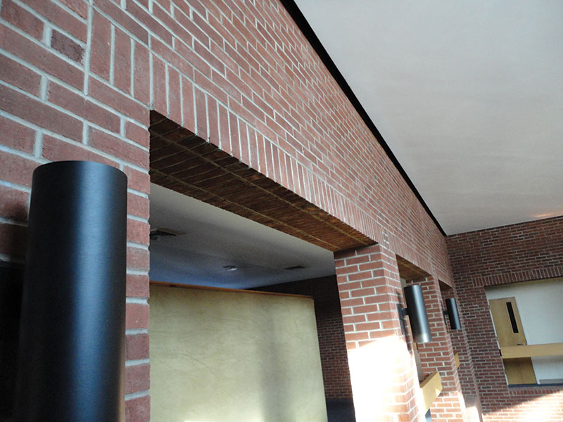
Figure 5. Interior openings with steel framing.
The brick beam solution for this condition in the 1980s was to provide a suspended brick beam from the steel framing (Figure 6) using stirrup hangers. The underside of the beam is all brick, similar to the interior brick beams previously described. Today, structural engineers might be tempted to use a patented system of steel hangers and embedded plates to create the hung beam. While those systems work very well, the procedure presented here is simple, straightforward and less expensive. The brick beam is not just hung weight from the steel beam; it is a structural element. The brick beam must carry load that is related to the construction sequence.
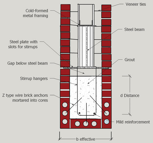
Figure 6. Interior brick beam with steel framing.
a. Construction
As with conventional steel-framed construction, the steel framing was installed first along with the metal deck for the floor and roof. For the floors, the concrete was placed; for the roof, the roofing system was installed.
As seen in Figure 6, there is a welded steel plate at the underside of the steel beam. It is intended to support the brick veneer at the level of the steel beam and above. In many projects, that plate is visible, and completes the underside of the beam and the opening. For this project, the plate is not visible because the brick beam encases the bottom of the steel framing.
The brick was installed in two stages. For the first stage, the brick veneer was constructed above the steel plate to maximize the dead load on the steel beam. For the second stage, the brick beam was constructed below the steel plate. One brick at the underside of the steel plate was left out at intervals to provide access for grouting the cavity of the brick beam. The access bricks were installed last. Because this design was used on the interior, no weeps, flashing or insulation were needed. The joint at the steel plate was mortared.
b. Load Distribution
Stage 1: The construction sequence dictates the design of the brick beam. Each steel beam first supports various dead loads (wDL Steel) that include its own self-weight (wbeam), the floor framing and metal deck (wframing), the remaining floor and roof dead load (wDL) and all the masonry wall above the steel plate (wbrick above). wDL Steel = ∑ (wbeam + wframing + wDL + wbrick above)
Stage 2: The brick beam was constructed aided by stirrup hangers from the steel plate. The hangers were installed during Stage 1 along with the upper brick veneer. The brick beam was formed on the bottom, similar to the interior brick beam previously described, and the reinforcement, ties, brick and grout were placed. Once masonry cured, the bottom forms were removed and the weight of the brick beam (wDL Brick beam) was distributed between the steel beam and the brick beam. The sharing is a result of the hangers from the steel plate into the brick beam that ensure equal deflections of the two structural members.
Any superimposed dead load or live load on the steel framing (wSuperimposed) is also shared with the brick beam. Therefore, the added load on the combined steel beam and brick beam (wLL) is represented by: wLL = wDL Brick beam + wSuperimposed.
Also, wLL = ws + wbb where ws is the proportion of load wLL assigned to the steel beam and wbb is the proportion of wLL assigned to the brick beam based upon consistent deflections. Knowing that the steel beam deflection is proportional to ws/EsIs and the brick beam is proportional to wbb/EbbIbb and that these are equal, it is possible to solve for ws and wbb.
ws = wLL x (EsIs)/(EsIs+EbbIbb)
wbb = wLL x (EbbIbb)/(EsIs+EbbIbb), or wbb = wLL – ws
Therefore, load sharing means the brick beam does not have to support all of wLL and results in the shallowest possible brick beam.
c. Design
The steel framing is designed in accordance with AISC provisions; the total load supported is wDL Steel + ws. Load factors should be applied to these service loads if Load Factor design methods are used.
Using the masonry code (TMS 402), the deflection of the steel beam should be limited to l/600 because it supports masonry.
In the 1980s, the code-allowable beam deflection was also limited to a maximum of 0.3 inches. That requirement has subsequently been deleted for reinforced masonry beams. Today’s structural engineer should still consider total deflection, so as not to cause cracking.
For the design of the brick beam, the total load is wbb = wLL – ws.
Brick beam design in the 1980s used only ASD. Today, the structural engineer can use ASD or Strength Design provisions. The d distance for design is as shown in Figure 6. The effective beam width includes the brick and the grout.
In addition to determining the flexural and shear reinforcement in Figure 6, the brick beam requires some additional detailing. Single leg Z-anchors are used with cored brick to improve the bond with the grouted portion of the beam.
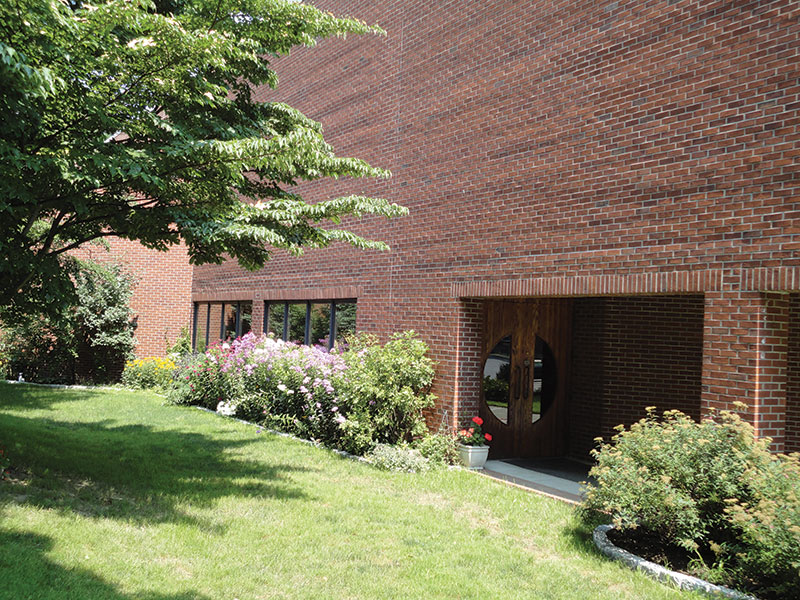
Figure 7. Exterior brick beams.
Exterior Brick Beam with Steel Framing
The construction sequence and design of the exterior brick beams match the methodology described for the interior brick beam with steel framing and the finished appearance (Figure 7). The primary difference is with the construction of the cold-formed metal framed wall (Figure 8). The original construction had batt insulation within the cold-formed framing, and flashing and weeps within the cavity. By modern standards, rigid insulation in the exterior cavity would be preferable, as seen in Figure 8. In addition, an air and moisture barrier as well as proper flashing and weeps are all required, but not shown.
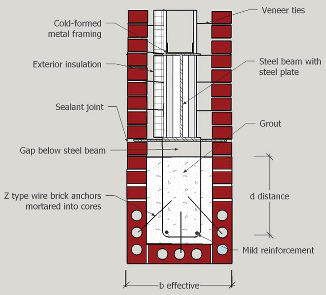
Figure 8. Exterior brick beam with steel framing.
Figure 9 shows the interior surface of the exterior brick beam, and a sealant joint at the bed joint with the steel plate is visible (arrow). Sealant joints were only installed in bed joints for the beams in the exterior walls, but mortar could have been used due to the composite nature of the steel beam and brick beam interaction.
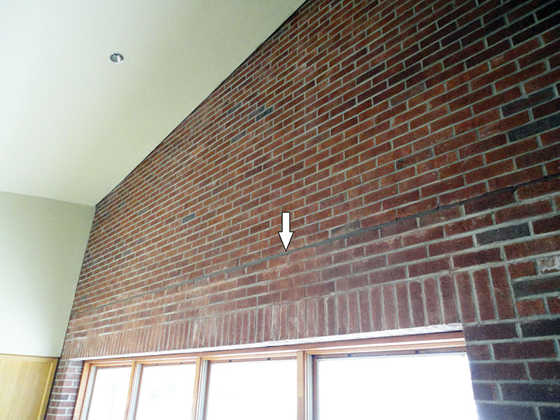
Figure 9. Interior of exterior wall beam.
Lessons Learned
1) After more than 30 years, the performance of the brick beams has been very good. The interior beams are in excellent shape and have required no maintenance. A couple of the exterior beams have had minor cracks and some repointing repairs. This is very impressive when considering life cycle costs.
2) Many engineers will remember the development of cavity walls with cold-formed metal framing in the 1970s and 1980s. Air and moisture barriers were not developed, and insulation placement and sheathing selection were not exactly what would be done today. Therefore, should problems occur with the wall system in the future, they will likely be attributed to the 1980s cavity wall construction and not the brick beams.
3) A primary lesson learned is that the placement of movement joints in veneers is very important and that our understanding of proper placement has improved over time. Figure 7 shows relatively few joints. By today’s standards, joints full height on the jambs of large openings would likely be used.
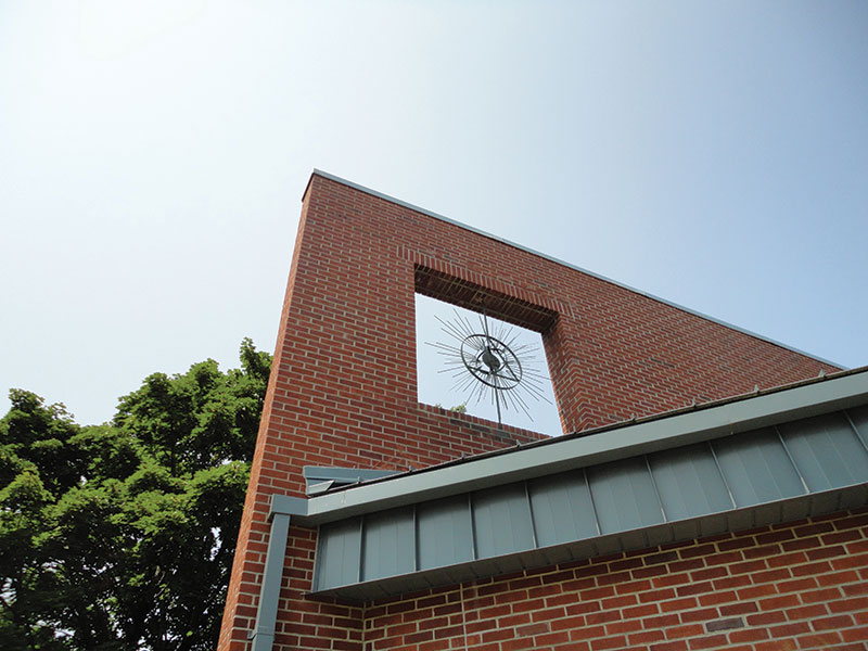
Figure 10. Aesthetic brick beam.
Summary
Overall, the brick beams on this project have performed well for over 30 years and still provide a wonderful aesthetic for the building (Figures 10 and 11). Once a methodology for load-sharing was developed, the design and construction procedures were simple and easy to implement. Given another opportunity today, the author would include the brick beams in a similar manner and incorporate the latest technology for the cavity wall construction for the exterior walls.
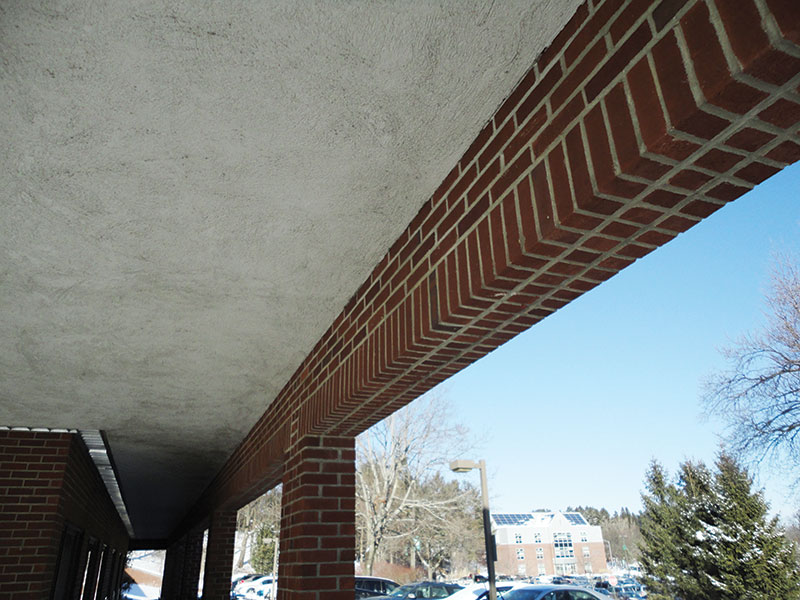
Figure 11. Brick beams at entry.
Remember the young architect? He’s Tom Birdsey, AIA, NCARB, LEED AP, now the President and CEO of EYP Architecture and Engineering, one of the top design firms in the US and internationally. Looks like making good masonry decisions early in one’s career can lead to great things!▪
Acknowledgements
Owner: Siena College, Loudonville, NY
Fr. Mark G. Reamer, Guardian, St. Bernadine of Siena Friary
Mark Frost, Assistant Vice President for Facilities Management
Structural Engineer of 1980s project: Ryan Biggs/Clark Davis, Clifton Park, NY