
NEHRP Technical Brief for Designers
Under the National Earthquake Hazards Reduction Program (NEHRP) and the stewardship of the National Institute of Standards and Technology (NIST), the Applied Technology Council (ATC) and the Consortium of Universities for Research in Earthquake Engineering (CUREE) have jointly prepared an excellent series of ten succinct and practical seismic design guides for practicing engineers, available for free online. Among the most recent additions is a guide entitled Seismic Design of Special Reinforced Masonry Shear Walls, A Guide for Practicing Engineers (referred to here as the Guide). The objective of the Guide is to synthesize model building code requirements and leading practitioner-recognized techniques, some of which may be forward-looking in recognition of on-going code development processes.
The Guide recognizes a fundamental challenge unique to masonry design. Other construction materials allow the structural designer to locate and size structural elements to achieve the desired or needed behavior, and the building is then constructed around these structural elements. Masonry, in contrast, serves simultaneously as architecture (defining a building’s external or internal appearance as well as its internal functional program), enclosure (defining a building’s external envelope), and structure (resisting vertical and lateral loads). The structural designer does not get to choose the configuration of these wall elements; instead, the other design factors dictate their locations and proportions. Thus, the structural designer must work with the elements that configure the space – must play with the cards that are dealt, in a manner of speaking. The designer must be able to anticipate the expected behavior of those elements so that he or she can adapt the design and detail each element appropriately to resist all required loading combinations to meet the intent of the code for stiffness, strength, and ductility. This is true for structural walls in all seismic design categories, but can be particularly challenging for special walls, because the expected level of ductility implied by the “special” designation simply may not be available.
To this end, the Guide focuses narrowly on the design of one classification of walls for one loading case: Special Reinforced Masonry Shear Walls subjected to in-plane seismic and gravity loads. Within this classification, it distinguishes between two fundamental types:
- Walls whose behavior is dominated by flexure, with reliable ductility and inelastic displacement capacity. These are flexure-dominated walls.
- Walls whose behavior, often for reasons beyond the control of the structural designer, are dominated by shear, with limited ductility capacity. These are shear-dominated walls.
With this as a continuing theme, the Guide then explores a number of important design issues affecting special walls, including:
- The use of different design methodologies permitted by the codes, including a brief introduction to new provisions for limit design.
- The effect of different plan configurations of walls on their expected behavior.
- The behavior of coupled walls and perforated walls.
- The influence of wall aspect ratio and axial loads.
- Guidance on the use of different analytical tools for masonry.
- The importance of maximum reinforcement limits to design.
- The influence of lap splices on behavior.
- The use of boundary elements.
- Detailing and constructability issues.
- Design process flow chart.
- What to do when shear dominated behavior is unavoidable.
This article touches on a few of these issues.
When Masonry Shear Walls are Special
The International Building Code (IBC 2012) requires the use of special reinforced masonry walls whenever masonry structural walls are used to resist seismic forces in new buildings assigned to Seismic Design Category D, E, or F. The design force levels are specified in Minimum Design Loads for Buildings and Other Structures (ASCE 7), and the design procedures and detailing requirements are addressed in the 2013 edition of Building Code Requirements for Masonry Structures (TMS 402). In ASCE 7, special walls are assigned the highest response modification factor, R, of any of the masonry shear wall types. For bearing wall systems R = 5; for building frame systems, R = 5.5. Inherent in the use of an R factor of 5 or more is the presumption of ductile behavior, associated with the development of plastic hinges with stable inelastic rotation capacity. The particular challenge of masonry seismic design addressed in the Guide is that the designer cannot presume that following the prescriptive requirements of TMS 402 will necessarily ensure the ductile, flexure-dominated behavior assumed in the determination of the design seismic loads.
Design Principles for Special Masonry Shear Walls
Shear Wall Configurations in Buildings
Masonry shear walls can have a variety of plan configurations. Most reinforced masonry codes and design guides focus on single, planar walls. Intersecting walls often create flanged configurations in T, L, I, C, or box shapes that can significantly affect the behavior. Typical walls also vary in elevation configuration, several of which are shown in Figure 1. Ultimately, the behavior of these different configurations is related to the collective behavior of multiple wall elements, each with its own aspect ratio, axial load, and reinforcement. These issues are discussed in detail in the Guide.
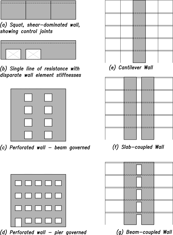
Figure 1. Elevations of typical masonry walls.
Design Methodologies
TMS 402 offers both Allowable Stress Design and Strength Design approaches. In the Guide, the primary emphasis is on Strength Design because TMS 402 addresses ductility requirements relevant to special walls more explicitly in that method. The Guide also provides a brief introduction to Limit Design, which is included in a new Appendix C to the 2013 edition of TMS 402.
Flexure- versus Shear-dominated Walls
Flexure-dominated elements are generally ductile. Shear-dominated elements are generally brittle, with failure characterized by diagonal shear cracks. Examples of each from laboratory tests are shown in the Guide. The implicit goal of TMS 402 is that special masonry shear walls be flexure-dominated and ductile. The code indirectly encourages designs that meet this goal through prescriptive requirements for distribution of reinforcement, limitations on bar diameters, maximum reinforcement restrictions, and other provisions.
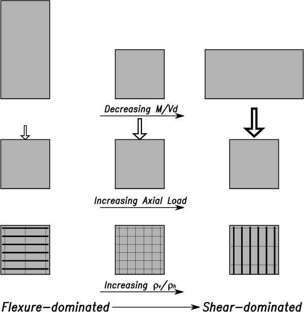
Figure 2. Conceptual illustration of the influence of shear-span ratio, axial load, and ratio of vertical to horizontal reinforcement on wall behavior.
Figure 2 illustrates the factors that lead to shear dominated behavior in a qualitative way. The Guide provides a more quantitative illustration of the influence of aspect ratio, axial load, and ratio of vertical to horizontal reinforcement on behavior.
Maximum Vertical Reinforcement Requirements
The requirements of TMS 402 §9.3.3.5 for strength design are intended to limit the amount of vertical reinforcement in shear walls to ensure that they exhibit ductile flexural behavior under seismic forces. The various limits of reinforcement stipulated in TMS 402 §9.3.3.5.1 through §9.3.3.5.4 are directly related to the respective ductility levels expected of ordinary, intermediate, and special walls.
In the design of special walls, it can be challenging to meet design requirements that limit the total amount of vertical reinforcement in special walls: the maximum permissible reinforcement percentage is much less for special walls than for ordinary walls, and it decreases further as the design axial force increases. These are all discussed in the Guide, together with discussion of special cases when maximum reinforcement requirements do not apply (e.g. for squat walls with Mu/(Vudv) < 1.0). The maximum reinforcement provisions may also be waived when certain provisions associated with boundary element reinforcement are satisfied.
Perforated Walls and the Limit Design Method
Perforated walls (Figures 1b, 1c, and 1d) can be particularly challenging because wall elements between openings normally have low shear-span to depth ratios, and may have high axial loads as well; they are therefore vulnerable to shear-dominated behavior. Appendix C (Limit Design) of TMS 402 provides an alternative way of designing special walls that is particularly beneficial for perforated walls, and addresses behavior modes explicitly.
Limit Design can be applied to individual lines of resistance in structures that are otherwise designed according to the strength design requirements of Chapter 9. It allows the structural designer to explicitly take into account the anticipated plastic mechanism of the wall system, to control the aspect ratios and reinforcement of wall elements to achieve the best behavior possible, and to detail the elements in accordance with the resulting flexure- or shear-dominated behavior. To determine the required design strengths of each wall segment, Limit Design requires plastic limit analysis, which is also discussed in the Guide.
Design Guidance
Following detailed discussion of behavior, the Guide offers clear guidance for the designer regarding both analysis and design of special reinforced masonry walls with simple and complex wall configurations. A flow chart provides a step by step presentation of the process. This includes consideration of out-of-plane loading, moisture change, and thermal effects in tandem with design for in-plane shear forces and axial loads in accordance with TMS 402. Ultimately, the designer is encouraged to take additional steps to establish whether the special wall is flexure-dominated (the implicit code intent for special walls) or shear-dominated (the unfortunate but unavoidable result of some architectural wall configurations). When a wall is shear-dominated, options are presented to achieve flexure dominated behavior, or, if that is not possible, to design for shear dominated behavior in a responsible way using a capacity design approach, and recognizing the reduced ductility of these wall elements. The designer should note that when shear-dominated masonry walls are designed with the understanding that they will attract forces larger than those consistent with a response modification factor, R, diaphragms and their connections must resist those larger forces as well.
Conclusion
It is hoped that practitioners who read Seismic Design of Special Reinforced Masonry Shear Walls, A Guide for Practicing Engineers will find not only a concise guide to current practice for special walls, but also a glimpse at the currently evolving direction of codes for seismic design of masonry. Reinforced masonry has unique challenges, and this short guide should make those challenges a bit more understandable for all.▪
Acknowledgements
The authors are grateful for the leadership and direction provided by Jon Heintz (ATC), Robert Reitherman (CUREE) and Steven McCabe (NIST). Particular thanks to Richard Klingner (Professor Emeritus, University of Texas, Austin), David Biggs (Biggs Consulting Engineering), and Steve Dill, (KPFF Consulting Engineers) for being an especially active and engaged review panel.
Dedication
This article is respectfully dedicated to the memory of Professor M.J.N. Priestley whose visionary work over many decades provided much of the foundation for the design principles discussed in the Guide.