
Engineers largely appreciate the differences afforded between allowable stress design (ASD) and ultimate strength design (LRFD) methods, and we generally follow the prescribed protocol for each procedure without much trouble. However, even though the ASD approach has been largely supplanted by LRFD, certain occasions require that we revisit the old ASD theory for reinforced concrete (or masonry). As such, it is appropriate that we recognize the subtle and not-so-subtle differences between the two.
Strength design for reinforced concrete has been the norm for many years. Its basic premise is that we design for a specific failure mechanism in the element and ensure that it is ductile. We commonly assume (among other things) that reinforcement yields and concrete crushes, preferably in that order. With this concept in mind, we can readily apply yield and crushing stresses to the steel and concrete, respectively, and develop overall capacity boundaries and limitations. We also apply load and strength reduction ([pmath]phi[/pmath]) factors to the design to ensure that the likelihood of breaching said boundaries and limitations is acceptably small.
The current strength design methods are a far cry from the previous working stress design approaches used for reinforced concrete. We no longer need to calculate depths to neutral axes based on transformed sections, nor do we need to use the parallel axis theorem to calculate a cracked moment of inertia. However, these traditional design approaches must still be examined as we look at serviceability.
The actual failure mechanism of the member is an extreme condition that is not easily adapted to ordinary serviceability conditions. Hence, strength design methods are not well-suited to addressing serviceability issues, since the goal of the latter is not to predict how much deformation will occur in steel as it actually yields or in concrete as it is actually being crushed. Working stress design methods typically use the same load combinations for strength and serviceability, but we must often develop two concurrent combinations, one set for strength design and another for serviceability, when using contemporary methods.
A potential error in the design of reinforced concrete is to mismatch design values and/or section properties between strength and serviceability design methods. An example of this is the depth to the neutral axis of a reinforced concrete beam, often assigned the variable c. For strength design, this occurs where the strain is zero when assuming a positive (compressive) strain of 0.003 (εcu) for the concrete on the top side, the net tensile strain (εt) in the rebar at the bottom side, and linear variation between them. The value of c is calculated by using similar triangles. The stress diagram to complement this is then easily derived from the assumed concrete crushing capacity and reinforcing steel yield strength, as shown in Figure 1.
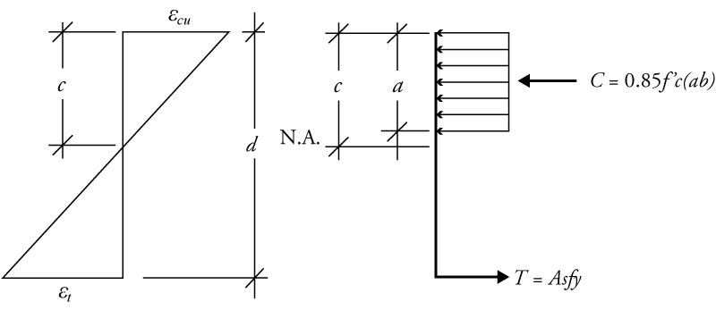
Figure 1. Strain and stress diagrams for concrete beam for strength design.
For serviceability design, strain may not necessarily be a consideration, but the stress diagram is taken as that shown in Figure 2. This would apply to both a serviceability limit state, for calculating cracked and effective section properties, and the maximum working stresses in the concrete and reinforcement, used to assess strength in the older methodology. For this diagram, the relationships are derived using transformed sections and assuming elastic behavior.
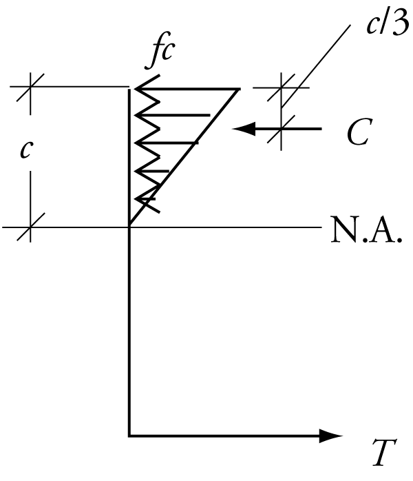
Figure 2. Serviceability stress diagram.
As an example, consider a 12-inch wide by 18-inch deep concrete beam (f ‘c = 4,000 psi) reinforced with three #6 bars (fy = 60,000 psi). Assuming that the span exceeds the limitations of table 9.5(a) in ACI 318-11, the strength design must be accompanied by a check for serviceability (deflection). For strength design, the depth to the neutral axis (c) is 2.28 inches. For serviceability, the depth to the neutral axis is nearly double this, at 4.51 inches. Hence, for valid design, the engineer must be cognizant of which limit state is under consideration (strength or serviceability).
In addition, the correct application of equations must accompany the method being used. Derived values between the approaches must never be interchanged. Interestingly, leading textbooks often assign the variable c as the depth to the neutral axis regardless of design consideration (strength vs. serviceability), hence the potential for confusion. In actuality, the behaviors reflected in the compared numerical models of the flexural mechanism are vastly different, one corresponding to the ultimate flexural failure of the member, the other to the stresses that may develop under normal service loading. One addresses behavior as the flexural strength threshold is breached, the other behavior that affects the comfort of the occupants that it supports.▪