
University of Kansas West Campus Structural Testing Laboratory
With an eye toward innovation and student collaboration, the University of Kansas (KU) School of Engineering wanted to significantly expand its scope of structural research. Opened in 2014, the Structural Testing Laboratory (Figure 1), located on the KU West Campus in Lawrence, is laying the groundwork for future innovation and offers one of the most advanced structural testing facilities in higher education. The 26,000-square-foot building is equipped with state-of-the-art instruments to accommodate full-scale systems and components and provide workshop spaces for student design and competition projects, as well as fabrication and machine shops.
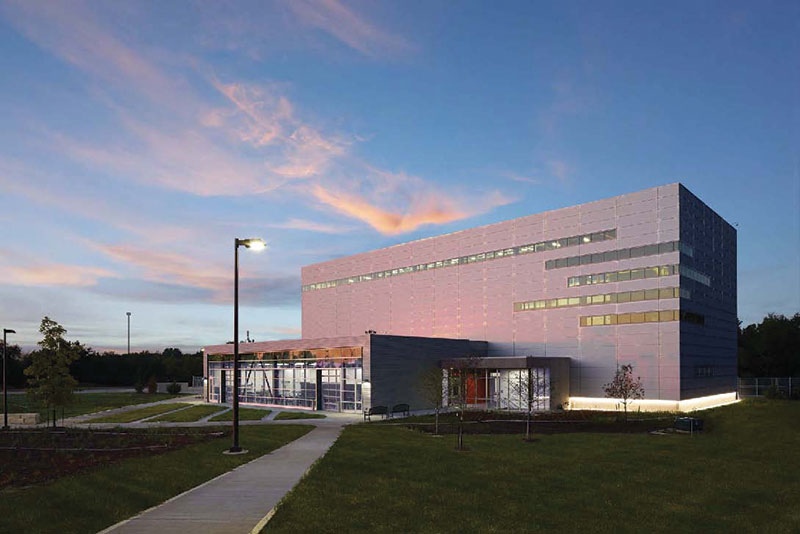
Figure 1. Structural Testing Laboratory – KU West Campus.
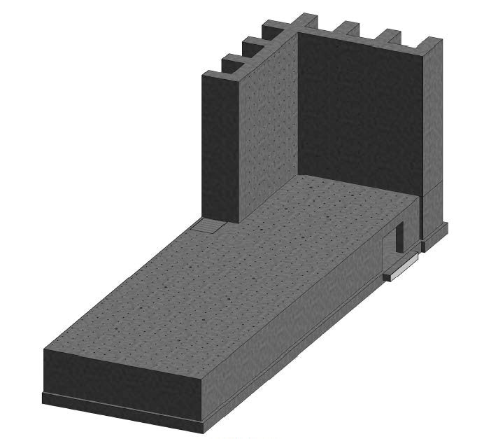
Figure 2. Strong floor and strong wall ISO. Courtesy of Burns & McDonnell.
The principal element of the facility consists of a strong floor and strong wall system (Figure 2) constructed of cast-in-place concrete with a specified strength of 5,000 psi at 28 days. The strong floor, which provides 7,000 square feet of test area, is a 3-foot-thick slab supported by basement walls. A heavily reinforced mat slab (Figure 3) was designed as the foundation to support the strong wall and strong floor system. As a result, the strong floor, basement walls, and mat foundation slab form a four-cell box girder that is 15 feet deep, 48 feet wide and 145 feet long. To secure test specimens, the strong floor has vertical through-slab tie-down holes (anchor points) spaced at 3 feet on center in both directions (Figure 4), each tie designed for an allowable vertical load of 100,000 pounds in tension or compression.
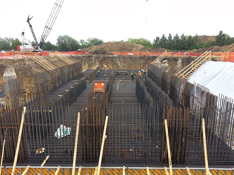
Figure 3. Concrete mat foundation.
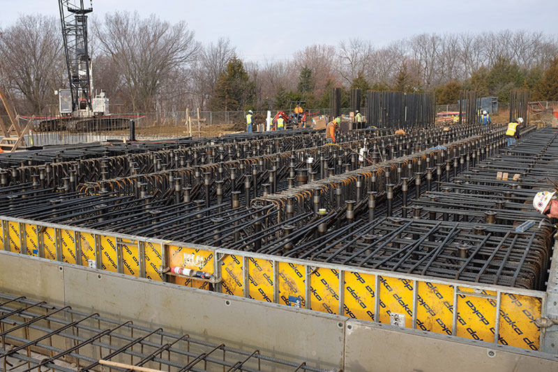
Figure 4. Strong floor with tie-down sleeves.
The 40-foot-tall strong wall – also called a reaction wall – is 4 feet thick and located at the east end of the strong floor, backed by 8-foot-deep buttresses spaced every 12 feet. Self-consolidating concrete and ASTM A416 Grade 270 post-tensioning tendons were used for both the wall and the buttresses (Figure 5), and the vertical reinforcing bars are ASTM A615 Grade 75. The strong wall is perforated with horizontal tie-down holes (anchor points), on the same grid as the strong floor, for the wall-mounted hydraulic actuators to apply lateral forces to the test specimens. The strong wall has an “L-shaped” profile, with two equal legs, to provide versatility for bi-directional testing. Each leg of the wall has a reaction area that is 36 feet long by 40 feet tall. The strong wall design provides an allowable lateral testing force of 880,000 pounds at each leg simultaneously, and thus an overall allowable lateral testing force of 1.76 million pounds. The strong floor and strong wall test area is equipped with two 20-ton capacity overhead cranes (Figure 6) to handle large and/or heavy test specimens, as well as hydraulic actuators and other equipment inside the laboratory.
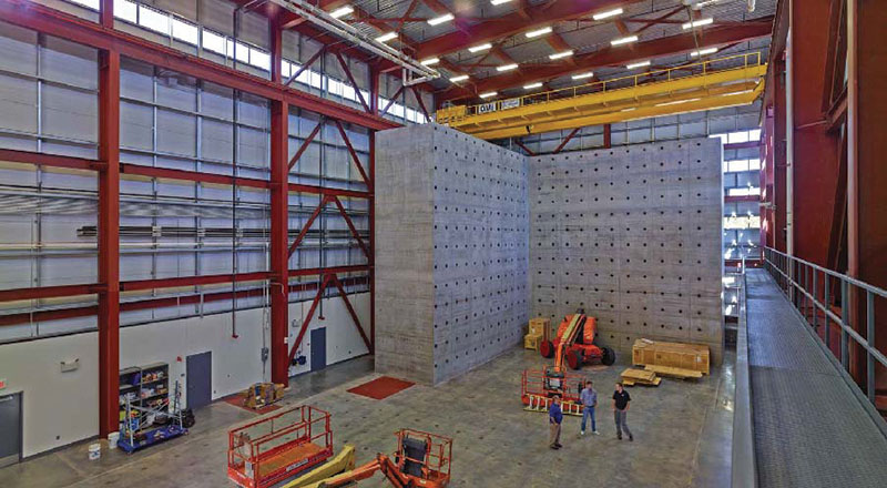
Figure 5. Strong wall.
The key engineering challenge of the project was the strong wall, which is a performance-driven, highly customized element. From the design perspective, at the very earliest stage of the project, the structural team had numerous meetings with the end-user groups including the Dean of the School of Engineering, professors, researchers, and graduate students. It was critical to learn from these groups their expectations, needs, and intentions regarding the strong wall. Information from these meetings set the design goals for the structural team to achieve in a constructible and economical way.
Because of the tremendous test forces to be placed on the strong wall, the design team and KU were concerned about potential cracking in the concrete surface. To address this concern, the design team performed concrete stress analysis utilizing computer software to determine the magnitude of the calculated stresses under various load combinations that were representative of different tests that could be performed. This identified “hot spots,” where the calculated tensile stress was greater than the allowable value. The next challenge presented to the structural engineer was how to reduce the high tensile stresses in a constructible manner. The solution was to place post-tensioning tendons in the vertical direction of the wall to introduce compressive forces.
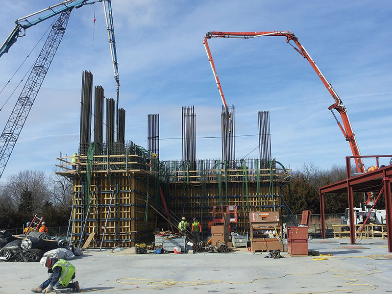
Figure 6. Test area with overhead cranes.
Once the design was complete, the strong wall also presented challenges from the construction perspective. The design criteria required a high-level concrete surface finish to satisfy both aesthetic and performance requirements. After further discussions with the construction contractor, the Kansas City office of Turner Construction, the team decided to utilize self-consolidating concrete for the wall. To ensure achievement of the desired concrete finishes and structural qualities, Turner built a large-scale mock-up of the strong wall on the site and then cut it open to determine how the self-consolidating concrete had performed. The results passed inspections with flying colors. Turner also developed a robust system of formwork that was adequate to hold the fresh concrete in place.
The $14.5-million facility has opened to positive reviews on campus. Research commitments are building, and KU’s structural labs will be fully committed by the time of this article’s publication according to Michael Branicky, the Dean of KU School of Engineering.▪
Project Team
Owner: The University of Kansas
Structural Engineer of Record: Burns & McDonnell
Prime Contract Holder: Treanor Arch.
Architect of Record: Burns & McDonnell
Construction Contractor: Turner Construction Company, Kansas City