
New York City
Near the flagship Hell Gate Bridge (STRUCTURE, October 2013), and crossing a former inlet between Wards and Randalls Islands, stands Gustav Lindenthal’s still-in-service 1915 Little Hell Gate Bridge; four unique skewed-deck truss spans of reverse parabolic bowstring arches. They are visually striking, sited as they are above flat land and below miles of high plate-girder viaducts. The total length between centers of the abutments is 1153.5 feet. Four-rail tracks operate on the 60-foot wide deck (Figure 1).

Figure 1. Flanked by viaduct spans, the century-old, still in service, distinctive Little Hell Gate Bridge reverse bowstring arch-spans suspend; with the Hell Gate and Triborough Bridges beyond. HAER NY 121-16, Weinstein, Photographer, 1996.
The War Department at that time regulated waterways and, as this arm of the East River was only a few feet deep and would not carry maritime traffic, it granted approvals in 1906 and 1912 for piers in the inlet and the use of falsework for the construction. Later, landfill from the Triborough Bridge project (Ammann, 1937) entirely filled the inlet.
Timber and Masonry for the Piers
The Portland cement concrete piers bear at four tons per square foot on foundations of hard strata, typically mica schist, encountered at a shallow depth of about 12-15 feet below mean low water. Henry Seaman, consulting engineer for the masonry on the project, described the process of the foundation and pier construction. Executed by the McClintic-Marshall Construction Company, piles were first driven into the river bottom to support the timber falsework of square posts and longitudinal bracing members. Next, for the piers near Little Hell Gate, heavy-timber crib open-cofferdams were built, and the area within leveled and dried. Concrete for the foundation of the piers was poured into forms set within the dams. Granite veneer covers the 12 vertical feet between mean high and low tide levels to protect the concrete piers from wear due to rapid current. The timber for the trestle, posts, and longitudinal bracing of the falsework was longleaf yellow pine.
And a great deal of it. The project used 360,000 board feet of heavy timber for falsework construction for each span. In discussions after completion of the project, some engineers suggested that floating the truss arches into place might have been more economical and efficient.
Formwork consisted of two-inch thick, ship-lap timber sheeting under four by eight-inch studs, held with wales and then bolted end-to-end for tensioning against leakage. The river pier shaft forms were barrel-hooped.
On Randalls Island, concrete was mixed on-site in a hopper below ground level to facilitate measuring, placed from derricks on platforms into buckets, and then transferred to the site; but on Wards Island, the concrete was placed by the relatively new practice of chuting. The concrete was conveyed to hoisting buckets up to a guy wire-supported 215-foot high, freestanding timber tower – the highest erected to date – and chuted to the end point. The completed piers are slightly battered at 1:15 and are 110 feet above mean high water, with 25-foot diameters at the water line.
The piers have horizontal and vertical steel reinforcing, at the time a comparatively recent and internationally little-understood technology, still based largely on trial and error. After 1900, several universities, the American Society of Civil Engineers, the Bureau of Standards, and the American Railway Engineering and Maintenance of Way (AREMA), among others, combined efforts to share the many emerging independent scientific laboratory analyses’ methods and test results, to understand and standardize the structural properties of bonded steel bars and concrete.
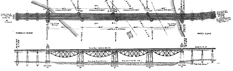
Figure 2. Lindenthal office drawing, Little Hell Gate Bridge, plan and elevation. The center skewed piers originally aligned with the inlet current. Two tracks load each truss. Transactions of ASCE, v. 82: 1918.
The Superstructure
The lightweight, simple, riveted web trusses are of lightweight Class A open-hearth structural steel. The reverse bow-string (under) deck trusses are constructed of 50-foot high parabolic and parallel arches, set 52 feet apart. The bottom tension chord is comprised of between ten to thirteen pinned eye-bars – the largest size forged to date, each at 38 feet long, 16 inches wide by about two inches thick, and connected by 16 inch-diameter pins tightly covered with cast-iron caps. Twenty-one of the 1,900 tons of annealed structural steel full-size eye-bars were tested before construction, with results of an average elastic limit of 36,500 pounds per square inch (psi) and an ultimate tensile strength of 61,800 psi. The truss structural steel is slightly higher at 66,000 psi, and has a yield point of 35,000 psi (Figures 2 and 3).
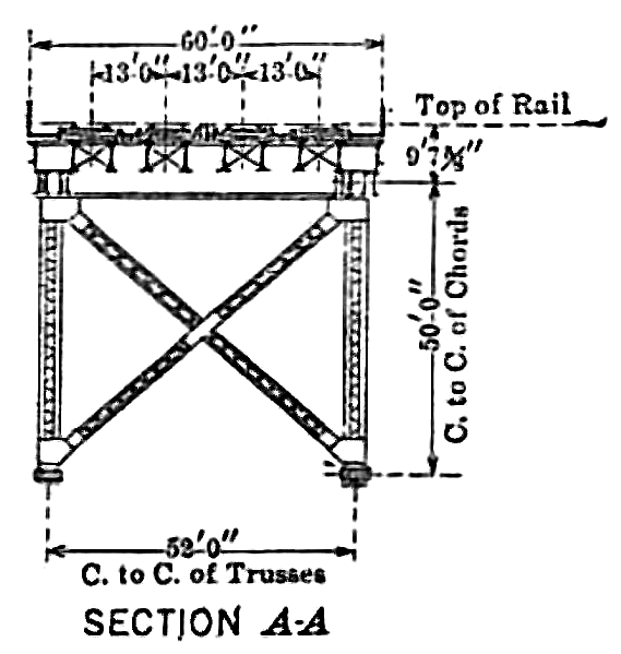
Figure 3. Lindenthal office detail, transverse section drawing. Sway-frames transfer lateral loads from the bottom chord via stiff diagonals to a heavy & rigid lateral system in plane with the top chord truss. Transactions of ASCE, v. 82: 1918.
There are no transverse supports at the bottom chords. Instead, stiff diagonal sway frames connected to each vertical web member angle up from the bottom chord, transferring wind loads up to a rigid and extra-heavy wind and vibration truss in plane with the top chord (Figure 4). The angles and joints connecting the uniform-sized truss members of the reverse bowstring arches are geometrically aligned, so as to equalize and distribute the dead loads.
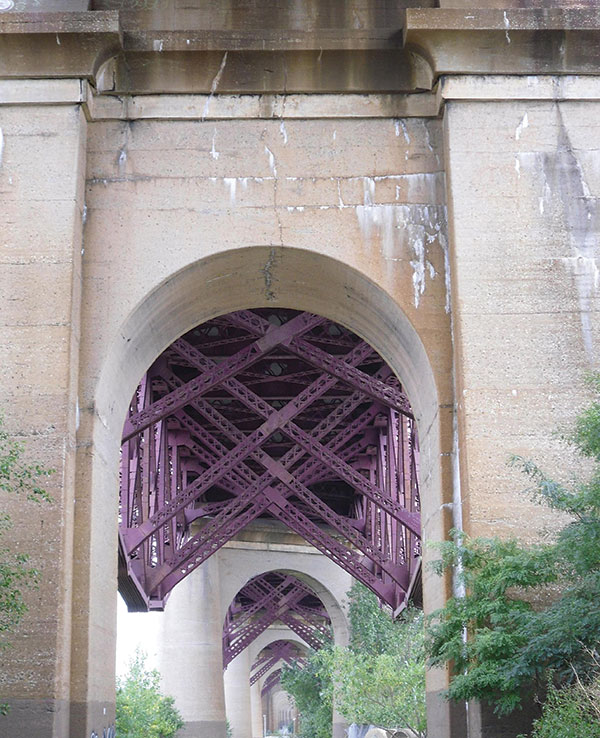
Figure 4. The Buttressed Barrel-Vault Arch at end pier 53, view to the north. The round river-piers and reverse arch spans stand and suspend beyond. Stiff steel sway frame diagonals provide lateral bracing. Concrete cracks, and white alkali-aggregate reaction deposits are active. Many tree roots stress shallow foundations.
The partially shaded below-deck truss arches experience less equally-distributed exposure to thermal expansion and contraction than would above-deck metal arches. The center of equilibrium, being 15 feet below the support points of the abutments and piers, contributes to the overall stability and rigidity of the structure under dead and live loading.
There are fixed bearings in the end spans at the abutments, whereas the center three skewed piers have moveable 24-inch high cast steel rocker bearings as reactions to one-sided loading. At the center pier, there is an expansion joint of about six inches. Secondary stresses are relatively large in the end panels.
McClintic-Marshall Construction Co. also handled the manufacturing and erection of all the steel for the trusses. Steel gantry travelers erected 11,250 tons of steel. Bents supported the material track at the top chord level, from which the truss members were lifted from below the track by the traveler. After the bottom chords were assembled and laid on adjustable camber blocking, the posts, diagonals and top chords were set in-place by gantry traveler. Total costs of the project were $990,000 (Figure 5).
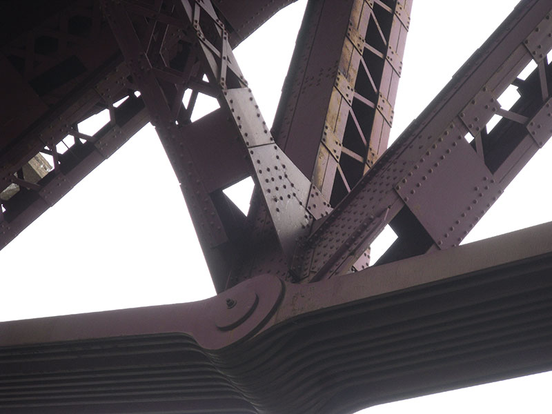
Figure 5. Detail, Little Hell Gate Reverse Bowstring Truss Bridge, 1915. Lower tension chord of eye-bars, with a view up to the deck, illustrating an array of structural steel truss members. Except for the eye-bars’ 16-inch diameter pins, the bridge is riveted to exacting specifications, at the high cost of 25 cents each.
The Floor
For the track floor, a timber floor of treated ties and a reinforced flat slab design were each initially considered, then rejected; for the first, due to the high contemporary cost of timber, and for the latter due to the design team’s cautiousness in depending upon reinforcement to any great extent to resist an assumed axle loading of 70,000 psi plus a 200 percent impact. While the aforementioned standardization studies were ongoing, there remained some distrust, specifically in the reliability and durability of the bonding between the steel and concrete to resist the stresses.
Instead, the floor is a solid ballasted type. A skeleton framework of eight-inch I-beams spaced at fifteen inches on center are placed across two stringers laid over one-eighth inch thick steel sheets per track. Five-eighths inch tie-rods, spaced ten inches apart, are fixed near the bottom of the I-beams. Three inches below the top, more reinforcing bars are placed longitudinally within the ten-inch thick concrete-encasement, or ballast-surrounded “tray”, poured flush to the bottom surface of the framework. There are embedded four-inch diameter vertically-aligned drain pipes. A two-inch thick timber plank walkway rests on the ends of the I-beams, between each track. The concrete is smooth troweled – one part Portland cement, two parts well-graded sand, and four parts of broken limestone (75 percent three-quarter inch stone and 25 percent screened as per the 1911 AREMA guidelines). Tests in 1915 revealed a compressive strength of 3,500 psi at 28 days. There is a less than 1.8 in 12 transverse slope, with no waterproofing materials.
Engineering Design
The three circular-in-section, skewed double-column river piers positioned between the squared abutment end piers are oriented longitudinally parallel to the inlet water flow, spaced about 296.5 feet apart. As the average spacing of all the other piers in the several miles-long viaduct spans are mostly in the 80+ foot range, the contrasting, large increase in spacing of the Little Hell Gate Bridge spans draws direct visual attention to the unique bridge. In addition, Lindenthal included simple end towers to further highlight the bridge.
Gustav Lindenthal considered the Little Hell Gate Bridge significant. The design elements, for example, of repeating various arch schemes throughout the project’s length, punctuated at nodes by outstanding bridges that made advancements in engineering, express aesthetic sensitivity along with structural purpose. Lindenthal intended his bridges to contrast with the many ubiquitous utilitarian truss rail bridges. The end towers, by architect Henry Hornbostel, are hollow, contain interior staircases, and include special crossbeams to carry the contact wires for the early electrification system. The end towers are diminutive as compared to the towers of the nearby Hell Gate Bridge, and therefore do not compete.
Post-Construction Testing and Maintenance
Loadings on the trusses were measured, and all seventy-eight truss connection pins that are under the cast iron caps were tested ultrasonically [ASTM E164] for concealed flaws in 2006. This technology reveals defects, voids and density of the steel. Readings reflecting off the steel via nondestructive, timed electrical waves in the 0.1 to 25 MHz range were then compared with control data. The tests revealed that the loading and all material capacities were in excess of both historic and current AREMA rating capacities. The century-old cast iron cap-covered structural steel truss joint pins showed no cracking.
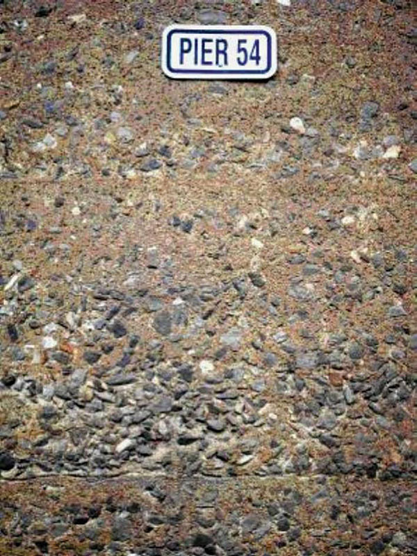
Figure 6. East face, pier 54. Permeable, century-old weathered concrete surface with exposed, large-sized aggregate which appears to have settled at the time of the pour. Note the one-part Portland cement to one-to-two parts fine-aggregate mortar slushing-edge between the horizontal pour layers. AREMA 1911 Specifications, in use at the time, stated that a uniform distribution of materials shall be obtained with the use of a straight slicing shovel after each pour.
Concrete surfaces, observed in an October 2014 site trip, exhibited weathering, spalling, cracking, and incipient rust stains, especially at the Little Hell Gate end piers. Much of the original dense concrete protective exterior surface layer (Figure 6) is eroded, exposing the interior to destructive alternating wet-dry cycles. Moisture is clearly penetrating the masonry via gravity and wind forces, surface tension, and capillary action. In addition, alkalis in the Portland cement, used in the concrete mix, are reacting with siliceous or carbonate elements in the aggregate. The chemical reaction develops new compounds as gelatinous white alkali within the masonry, which then expands through the masonry to harden on the exterior surfaces. While Portland cement was generally in use by c. 1890, its uniformity and alkali content varied considerably. The reaction phenomenon would be researched after c. 1916, when widespread reports of concrete deterioration emerged. The research continued into the 1950s, at which time the exact science behind the reaction was still little understood (Figures 7 and 8).
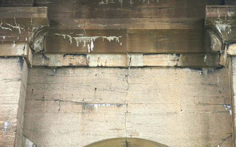
Figure 7. South face end pier 49. Vertical and horizontal popout-cracking, with ongoing severe spalling and alkali-aggregate reaction evident. New compounds from the reaction expand inside the masonry mass; the resulting localized pressure-zones result in microfracturing and spalling of the structure, here seen in the re-entrant spandrel-wall below the cornice. Cracks are oriented parallel to the bars. Volume changes and strength-loss of the masonry-mass are in progress.
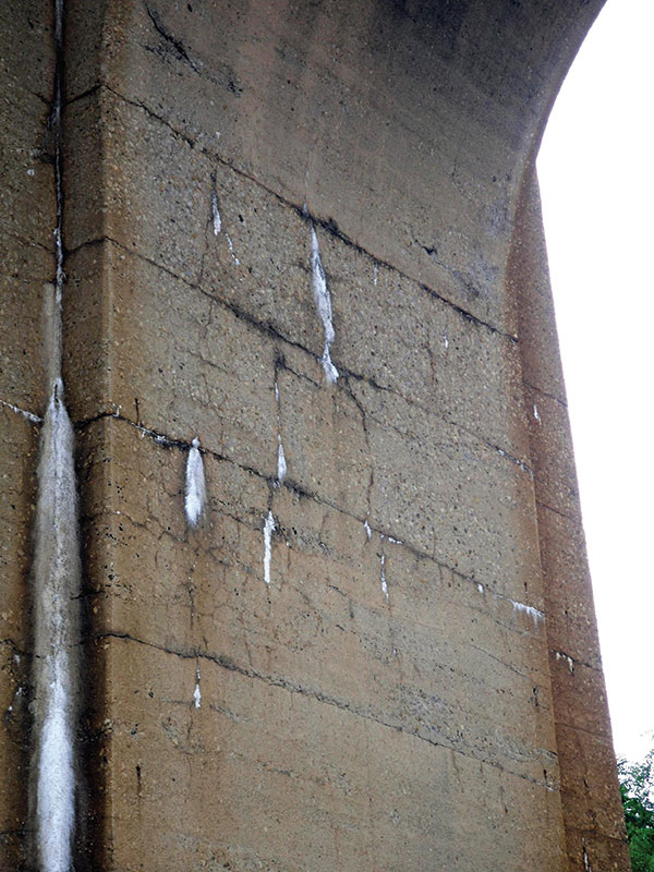
Figure 8. Cylindrical-vault abutment sidewall, end pier 53. Detail of active and desiccated white alkali deposits from reactions between inherent chemicals in the cement and aggregate, thermal effects, polluted air, and moisture. Note the resulting pattern-cracking below the arch springing. Increasing permeability of the mass and incipient oxidation of reinforcement are contributing to the cracking.
Cracks and strength-loss result from masonry-mass volume changes. At each end pier there is a continuous vertical crack leading all the way down on both faces of the re-entrant spandrel walls and cornices, and following through the vertex (center) of the six-foot deep barrel-vaulted arch-intrados (soffit), reflecting some displacement of the heavy masonry structural elements. Through-cracks have developed near the springing points in the same manner as at the vertex. Hinges have formed where the lines of thrust converge within the arch-structure boundaries. Three hinges produce a statically determinate structure with changing equilibrium and shifting thrust moving increasingly horizontally through the hinging points. Internal and external degradations develop instability and eventual overloading of the structure.
The eradication of the Little Hell Gate inlet in 1930s mitigated some of the bridge’s environmental hazards – such as continued exposures to corrosion-causing salty estuarial waters, and scouring at the piers – and contributed in part to the bridge’s low maintenance record. At the time, advancements occurred in paint technology, which indicated that applying a slightly alkaline paint and providing positive electrolytic action via added sulfate of lead, or zinc oxide mixed with linseed oil, was most protective. Lindenthal knew this, as he used these types of paints on his other metal bridges as far back as 1883. The bridge was painted in 1939 and 1995, with only minor repairs to the steel in 1992. The metal truss is nearly free of rust. The Centennial of this historic and significant project is in 2015.▪