
Pinnacle Bank Arena, Lincoln, Nebraska
Through the use of cold formed steel (CFS) framing, the corners of a rigid polygonal concrete structure can be smoothed and transformed into the gentle curve of an ellipse, enlivening the architect’s vision and creating a landmark structure in an up-and-coming neighborhood.
Project Overview
Constructed as part of Lincoln’s West Haymarket Redevelopment Project, the new Pinnacle Bank Arena was completed August 2013. The 470,400 square foot multi-use event complex will not only serve as the new host for the University of Nebraska’s men’s and women’s basketball games, but also as a venue for year-round entertainment. Concerts, touring acts, and family productions will utilize the arena’s three public concourses and seating capacity for up to 15,900 guests.
The new indoor arena is a seven level concrete structure wrapped in a metal panel and glass curtain wall façade. The inner, octagonal concrete super structure is enclosed by cold formed steel framing, which transforms the outer shape into a tri-radial ellipse. The facility combines “space-frame” panelized walls at the upper collar section with “stick-framed” walls at the lower collar area. Adjacent CFS framing with long span sloping walls were also “stick built” due to size and site constraints.
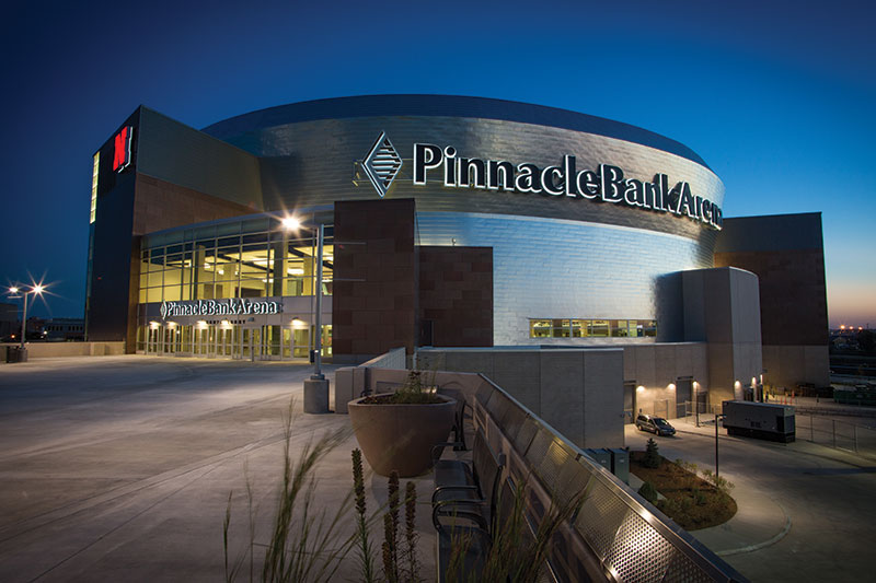
Figure 1. Pinnacle Bank Arena rendering.
Project Challenges/Solutions
Various architectural design considerations, structural requirements, and construction obstacles had to be addressed throughout the cold formed steel design process to keep the project on schedule and on budget:
- Tri-Radial Elliptical Façade
- Panelized Space Frames
- Special Construction Loading Requirements
- Sloping Wall Studs
- Staggered Openings at Bypass Wall Conditions
- Connection Requirements
- Large Duct Opening within Space Frame Panels
The use of cold formed steel space frames was determined to be the best method to accommodate the changing radius of the elliptical façade and to address the sloping exterior at the upper collar. Each frame was modeled and analyzed at its maximum and minimum offset distance (from the building super structure) using RISA 3D. Various load cases and load combinations were applied to the space frames per ASCE 7-05. Special construction loading considerations were necessary for this project due to the volume of cold formed steel framing required, the duration of time to install and enclose the building, and the limited access to the exterior cold formed steel façade throughout construction. During the construction process, the building would only be partially enclosed for a substantial period of time, making it necessary to engineer the space frames to withstand the higher wind loads associated with this type of exposure. Each space frame was designed to support temporary construction platforms located on the horizontal frame members. The platforms were necessary to provide access to the outside of the wall studs until the exterior was completed. The frames were designed to be constructed into wall panels and lifted into place by crane (Figure 4). As a result, the space frame panels had to be analyzed with reactions at the crane “pick points,” in addition to the standard reactions at building supports. Another construction complication was the large offsets between the concrete super structure and the outside face of the exterior wall studs. Each space frame panel was 50 feet tall by 12 feet wide with offsets varying in depth from 6 feet to 20 feet. Frames were spaced at 16 inches on center throughout, with of a variety of stud depths and thicknesses depending upon location (Figure 2).
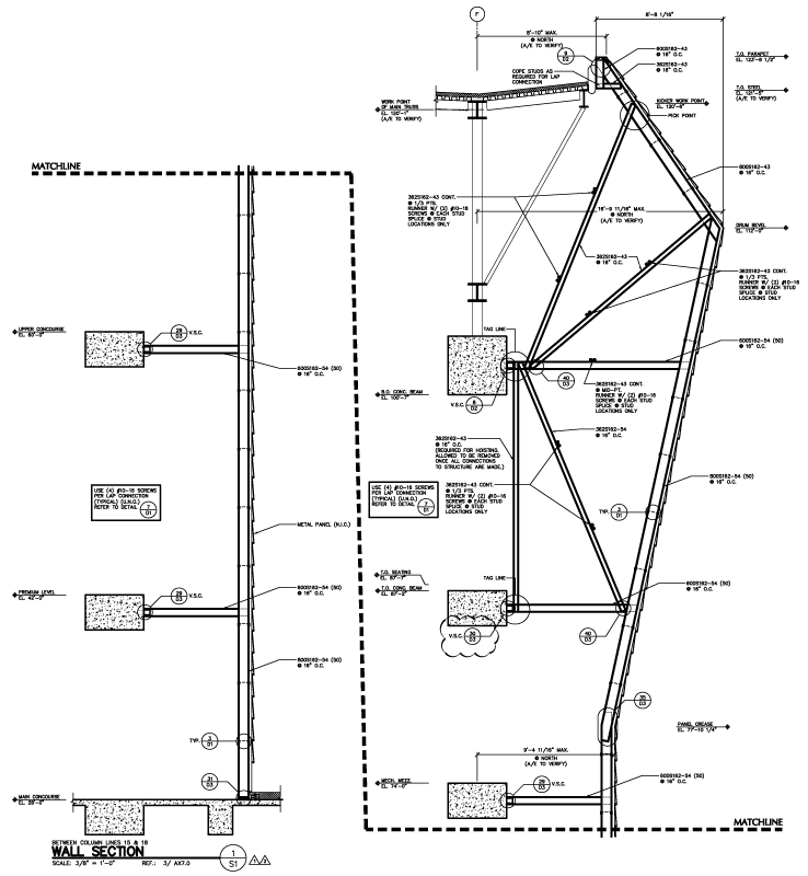
Figure 2. Typical CAD wall section showing “Space Frame” at upper collar.
The lower building collar has portions of curved, sloping walls that bypass the structure. Within these walls, staggered windows of different lengths and elevations require this section to be stick framed in a more traditional manner, in lieu of panelization. Engineering the framing around each of these window openings is difficult since the windows are positioned in locations that do not allow the jamb studs to run continuous from top to bottom; jambs are often interrupted by another window opening above or below (Figure 3). To accurately engineer the headers, jambs, and sills at these misaligned openings requires intricate load trace calculations. Large concentrated loads on headers and sills from adjacent jamb reactions caused the opening framing to be heavier than typical when compared to openings in a stacked configuration.
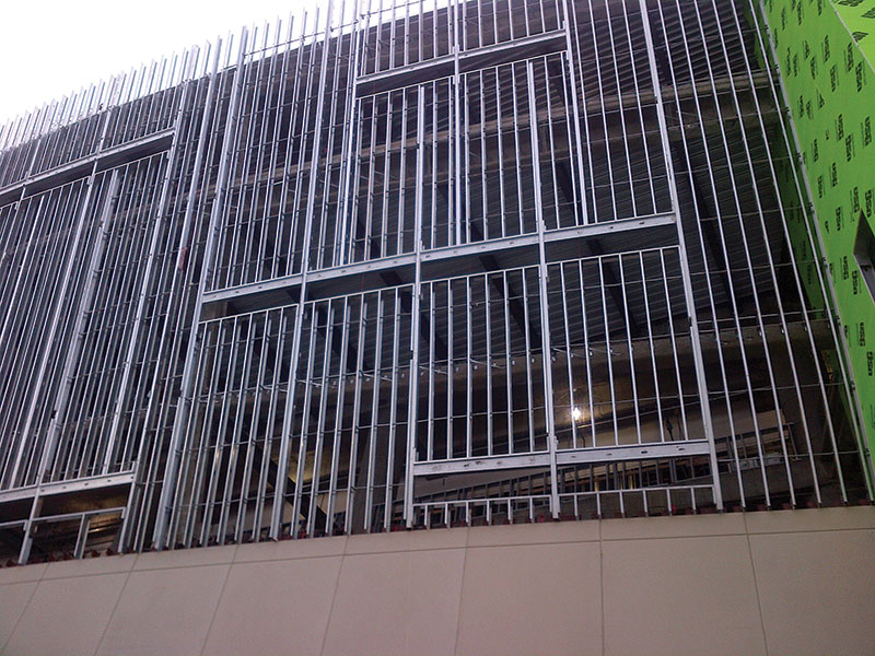
Figure 3. Staggered stick-framed openings at the west building elevation.
The building’s super structure was engineered to laterally support the exterior building façade; however, all gravity loads needed to be transferred and relieved at the main concourse level. The cold formed steel space frame construction at the upper collar allows for the transfer of gravity loads through trussed sloping members down to the base connection without gravity loading intermediate levels. For both the space frame panels at the upper collar and the stick framed walls at the lower collar, the bypass connections to the super structure are made with vertical slide clip connections at all levels above the main concourse (Figure 2). The vertical slide clip (VSC) connections allow each level to deflect independently under gravity loading without any vertical load transfer to the attached framing.
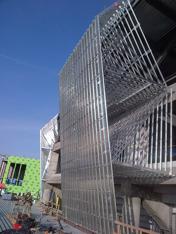
Figure 4. Installed CFS wall panel.
The large facility requires systems of an equal scale to meet its high electrical, mechanical and plumbing demands. To avoid possible conflicts with various systems’ piping and ductwork, BIM software was used during the design phase to coordinate CFS framing with the building systems and provide clash detection prior to installation. This extra measure enabled multiple disciplines to work together and provide solutions in the early stages of the project, preventing delays during the construction phase. One specific item discovered using BIM was interference between the space frames and a large ventilation duct in the upper seating bowl of the arena (Figure 5). This discovery resulted in the addition of structural steel during the design phase, to allow for CFS space frame attachment around the ducts, avoiding potential costly field modifications during construction.
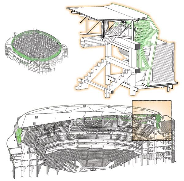
Figure 5. BIM rendering of Pinnacle Bank Arena upper seating bowl.
The unique and complex layout of the arena also had an impact on the construction methods used. The space frame wall panels were constructed on a “jig table” during the day, and lifted into place by crane in the evening. A concrete slab was poured on-site to create a jig table large enough to layout four panels at one time (Figure 6). Each panel was constructed of ten individual frames, which were tied together with cold rolled channel to create space frame wall panels. The panels were lifted by a crane via engineered pick points, clipped to the super structure and lapped on to previously installed vertical stud framing. A total of 96 space frame wall panels were required to complete the construction of the structure’s upper collar.
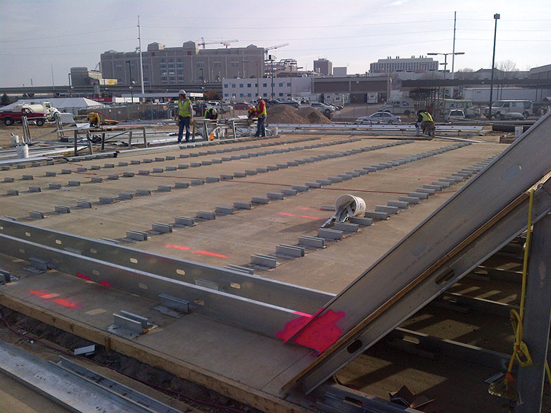
Figure 6. “Jig Table” used for on-site panel construction.
Conclusion
The ideal combination of construction materials, along with coordination of multiple disciplines, ensured the Pinnacle Bank Arena was successfully completed on time. The use of innovative design concepts and construction practices were valuable in addressing a challenging building design and keeping the project on schedule. The CFS framing was utilized to accommodate the ever-changing slopes of the exterior metal wall panels and the tri-radial curve of the building’s footprint. Its lightweight characteristic allowed contractors to more easily build and transport large CFS wall assemblies, lending favorably to wall panelization. As demonstrated during construction of the Pinnacle Bank Arena, specialized and complex panel framing can be constructed in a controlled environment, then lifted, and connected to the structure. Benefits of the panelized construction method include increased quality assurance, decreased production time, and overall project safety.
Innovative designs often require engineers and contractors to utilize building materials in new ways, reinforcing the importance of proper material selection. When selecting building construction materials, consideration should be given not only to achieving the desired building aesthetics, but also to project constructability.▪
Project Team:
Owner: PC Sports
Structural Engineer of Record: Buro Happold Consulting Engineers PC
Architect of Record: DLR Group
Construction Manager: Mortenson Construction
Specialty Structural EOR for CFS Framing: Excel Engineering, Inc.
Wall Panel Fabricator/CFS Framing Contractor: Falewitch Construction Services, Inc.