
Bethel Missionary Baptist Church was founded in the nineteenth century by Reverend Jack Yates, an early leader of Houston’s African American community. Located in Freedmen’s Town, a post-Civil War Houston neighborhood founded by freed slaves, the church was the first constructed by former slaves, with the earliest portion constructed in the 1890s.
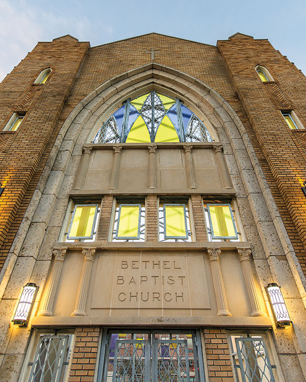
Figure 1
The first two church buildings were destroyed, and in 1923 a third single story church building was erected. In 1950, second and third stories were added. The sanctuary was designed by James M. Thomas, a prominent architect of African American churches. In January 2005, a fire gutted the interior of the historic structure, collapsing the interior framing and roof, leaving only the exterior masonry walls in place. The structure sat exposed and abandoned until 2009, when the City of Houston purchased the property to convert the former church into a community park (Figure 2).
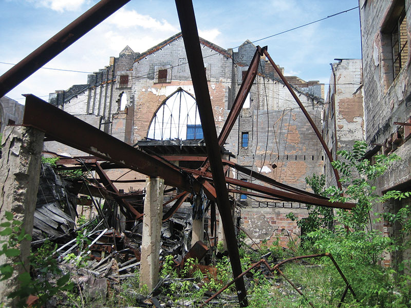
Figure 2
The remaining walls consist of two distinct constructions. The 1923 single story is a reinforced concrete frame in-filled with structural clay tile with a brick veneer. These walls were present at the base of the east, west, and south walls. In 1950, when the second and third stories were added, the north wall of the building was re-clad with a concrete masonry unit (CMU) and brick cavity wall system, and the new north façade was increased to a height of 50 feet. The CMU and brick cavity walls were also constructed on top of the existing 1923 walls on the east, west, and south elevations during the 1950 renovation.
Before Restoration, Protection
Walter P Moore of Houston, Texas, was initially retained to provide nondestructive testing services to evaluate the conditions of the existing masonry walls and develop strengthening solutions as necessary. However, once an initial site visit was conducted, the first challenge of the project became evident; access into the site to evaluate the masonry walls was nearly impossible due to the collapsed framing and debris that still remained from the 2005 fire, and a large crack in the 50-foot tall brick veneer running from the base of the wall to the top was visible at the northeast corner of the building (Figure 3). The deteriorating façade immediately adjacent to the pedestrian sidewalk posed a potential risk to public safety. Before any assessment could be performed, the engineering team made recommendations to the City to immediately close the street to traffic and temporarily brace the existing walls. Emergency shoring and bracing was designed and installed within a 24-hour period to protect the public and the structure.
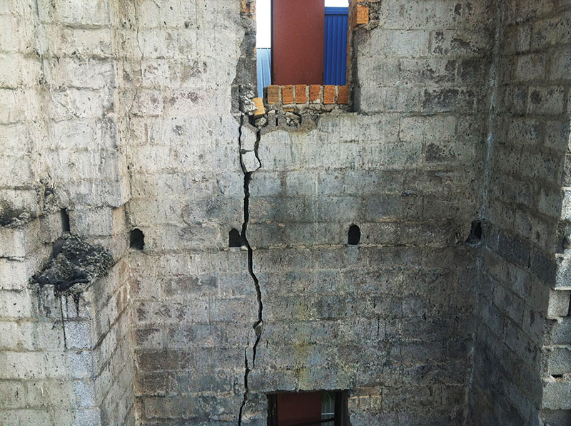
Figure 3
Determining Basis for Design
The biggest challenge in any restoration project is developing information about unknown conditions. Once the walls were stabilized, a comprehensive visual condition assessment was performed to document the distress conditions for repair and understand the wall construction. Given the fire-damaged state of these walls, understanding the appropriate masonry strength to use in design was fundamental. A combination of flat-jack tests and unit compressive strength tests were utilized to determine the masonry material capacities needed for design.
Flat jack testing is a nondestructive technique where masonry compressive and shear strengths are evaluated in-situ. When measuring compressive strengths, the test consists of routing out a horizontal mortar joint to allow a calibrated steel bladder to be inserted into the joint. For shear strength tests, a vertical joint is tested. Linear variable differential transformers (LVDTs) are mounted to wall surface and the bladder then “inflated” hydraulically (Figure 4). The hydraulic pressure and displacements are measured and a stress-strain relationship is developed.
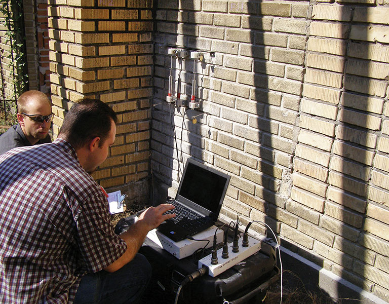
Figure 4
The laboratory testing data showed that the historic brick had a compressive strength of 1,600 psi. The modern brick in the building had a compressive strength of 2,000 psi, which is consistent with the minimum compression strength for Grade S-I, S-II bricks, while Grade N-1 and N-2 bricks commonly used in modern construction have a minimum compressive strength of 3,000 psi.
In historic preservations, the designer always has to specify materials that conform to, or are as close as possible to, those used in the original construction. For this project, it was anticipated that repointing deteriorated mortar joints would be necessary, so a mortar analysis was performed. Three mortar samples were excised from the structure and analyzed by acid digestion of the binder and sieve analysis of the aggregate in accordance with ASTM C136. This analysis determined the starting proportions for the mortar specified in the design documents should be 1: 1¼: 5½ (Portland cement : lime : aggregate). In addition, the color and gradation of the mortar aggregate were determined, which allowed the contractor to closely match the original mortar properties and aesthetics (Figure 5).
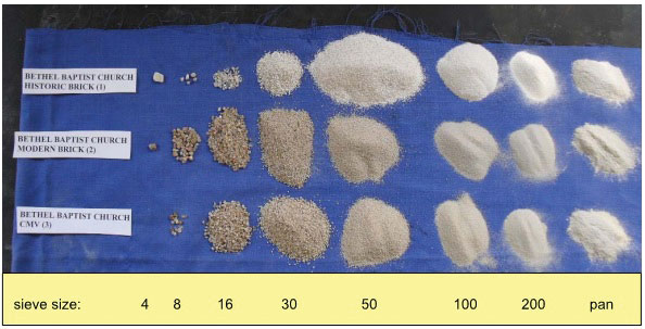
Figure 5
Wall Strengthening in Plain Sight
The engineering assessment program determined that the CMU back-up walls and structural clay tiles were in poor condition as a result of the fire, resulting in a dangerous condition. Significant cracking was evident throughout the back-up wall system, and large portions of the wall were unreinforced, including the 50-foot tall north wall. At several locations, the brick ties that anchor the brick veneer to the back-up wall, installed during the 1950 construction, had corroded and failed. Failure was likely prior to the fire and was due to the age of the building, but resulted in veneer that was separating from the back-up.
In keeping with the historic nature of the walls, a strengthening solution had to be designed that would not alter the existing aesthetics and would minimize the extent of replacement in the building veneer. To accomplish this objective, the design team proposed a galvanized steel frame that would visually recall the original gabled roof lines of the church, with new metal panels and poly-resin glass panels installed in the existing windows and door openings (Figure 1).
The existing walls would have to be strengthened to span between the girts of the new frame for the loads imposed by the 110-mph hurricane wind speeds required by the building code (IBC 2006 modified with City of Houston amendments). This design requirement alone would be challenging enough for a heavily damaged masonry structure. However, because the walls themselves would be exposed and without interior finishes, strengthening would need to be “hidden in plain sight” to community park patrons while not visibly altering the appearance of the walls. The design team developed a repair solution that consisted of strengthening of the back-up wall and pinning the existing brick veneer to the strengthened back-up. With this strengthening accomplished, a ferrocement finish was applied that provided additional strengthening and added to a clean appearance for the interior of the park.
At the base of the walls in the 1923 construction, a new, reinforced CMU back-up wall was constructed to “sandwich” the existing structural clay tile in-fill; removing this infill could have potentially compromised portions of the wall supported above it. Stainless steel helical anchors were then driven through the existing veneer, the existing structural clay tile, and into the new back-up wall beyond.
In the 1950 construction, the existing CMU back-up walls were reinforced by removing the interior shell of the CMU and grouting in new vertical reinforcing bars doweled into the existing grade beams. Large cracks in the existing CMU back-up were reinforced by routing out the horizontal grout and installing stainless steel helical ties across the crack. Once this crack reinforcement was installed, the grout line was re-pointed and the crack itself was then grouted. Cracks through the exterior brick were also treated in this manner, and the brick veneer then pinned using helical anchors back to the strengthened back-up wall.
A ferrocement coating was then applied to provide lateral reinforcement to the CMU back-up wall and provide a uniform finish to the interior of the park walls (Figure 6). Galvanized welded wire reinforcement was pinned to the interior faces of the walls, and a 2-inch thick shotcrete coating was applied. At window openings and the tops of the walls, the ferrocement coating was extended around the edges of the openings to provide clean and aesthetically pleasing terminations. The ferrocement was given a drag finish for a relatively smooth wall surface that resembled a stucco wall finish. A cream colored elastomeric finish coating was specified by the design team to brighten the interior finish and contrast against the new multi-colored fenestrations.
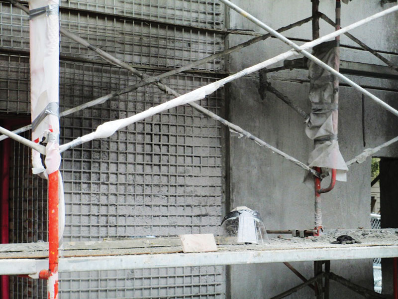
Figure 6
While this strengthening ensured that the historic walls would stand through the hurricanes that are possible in the Houston area, a number of other details were required to enhance the appearance of the park and preserve key architectural elements of the walls. Cast stone panels installed in the north wall required patches to repair spalls and restore these panels. Existing lintels over door and window openings in the 1923 construction were removed and replaced since corrosion of the original lintels had resulted in rust-jacking and cracking.
Once construction began, it became evident that each wall opening varied from the next. Each new fenestration required special detailing to connect to the existing walls. To anchor the new window and door panels, structural clay tile had to be removed between the new CMU back-up wall and the existing brick veneer. Helical anchors were then installed between the brick and the CMU back-up, and the cavity filled as a part of the ferrocement construction. This provided a solid substrate into which anchors for the new panels could be installed.
Coordination between the City, the design team and the contractor was a fundamental component to successfully delivering this project. Mock-ups of the ferrocement installation, coatings, and window terminations were constructed at key milestones in the project. These mock-ups allowed the design team and the Owner to meet, and review with the Contractor, issues related to aesthetics and constructability before getting approval by the Owner and design team. In addition, routine field observations by the design team throughout construction identified unknown conditions and developed alternate repairs and details as needed.
All told, the construction lasted just over one year, with the ribbon cutting for the new park on December 15, 2013. The completed Bethel Park features concrete and brick walkways, installation of an artificial turf interior courtyard, and site amenities including raised fountains, seat walls, benches, lighting, fencing, landscaping and irrigation. A particular highlight of the park is the historic education panels mounted throughout the space.
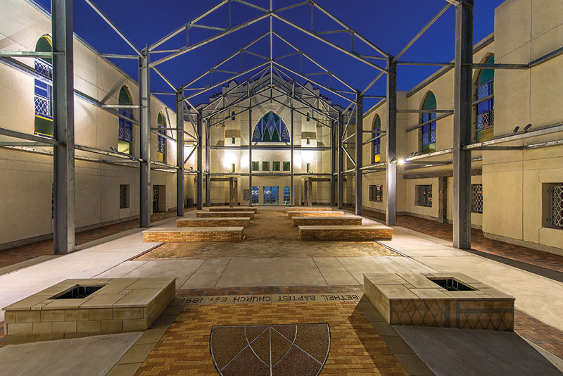
Figure 7
Conclusion
Severely damaged by fire, abandoned, but not forgotten by its community and congregation, Bethel Park preserves an important part of Texas and African-American history. Preserving heavily damaged, unreinforced masonry walls, protecting the public safety, and creating a new community space in which the original church walls were integrated were significant challenges for the design team. The unique strengthening techniques made it possible to have exposed masonry walls that contribute to the overall park aesthetic (Figures 7 and 8). The total project cost with property acquisition, bracing, design and park development was $4.7 million. The cost of strengthening the structure was $2.1 million, about half the total construction cost.▪
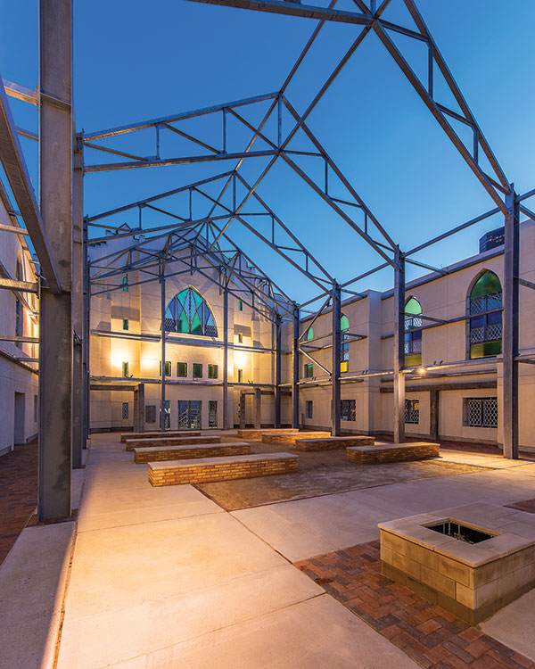
Figure 8
Project Team
Owner: City of Houston – Parks Department, Houston, TX
Structural Engineer for Masonry Wall Repairs: Walter P Moore, Houston, TX
Structural Engineer for Structural Steel Framing: Henderson + Rogers, Inc., Houston, TX
Architect of Record: PGAL, Houston, TX
General Contractor: JE Dunn, Houston, TX
Masonry Subcontractor: United Restoration & Preservation, Houston, TX
Landscape Architect: White Oak Studios, Houston, TX