
Compression and Form Finding
Traditional structures are linear, stiff, restricted, heavy, and inefficient; lightweight structures, on the other hand – whether in fabric, cable, timber, concrete or stone – are nonlinear, long-spanning, flexible, highly efficient, and environmentally friendly. This series shows how, when form follows force as well as function, the result is a structure that soars. The first article was published in the November 2014 issue of STRUCTURE®. This second article looks at compression structures and form-finding techniques for getting the optimum structural form. It will also look at the important step of optimizing the geometry for lightweight structures.
Compression Structures
Compression-only structures take the familiar form of walls, arches, shells and grid shells. Unlike tension-only structures that deflect to balance the loads, compression-only structures do not have this luxury, as any movement increases the risk of buckling. This is a major risk for masonry structures, as they have little or no bending capacity other than that provided by the compression thrust. For the Gothic cathedrals of old, the soaring columns needed stabilizing with flying buttresses (Figure 1).
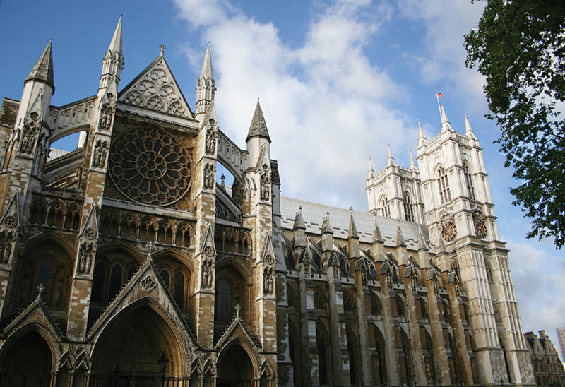
Figure 1. Westminster Abbey.
Compare this to the Sagrada Familia cathedral by the Catalonian architect/engineer Antonio Gaudí. Here the columns are angled so as to take the loads in direct compression and thus avoid the horizontal reactions that would necessitate buttressing. The end result is something much more natural-looking (Figure 2).
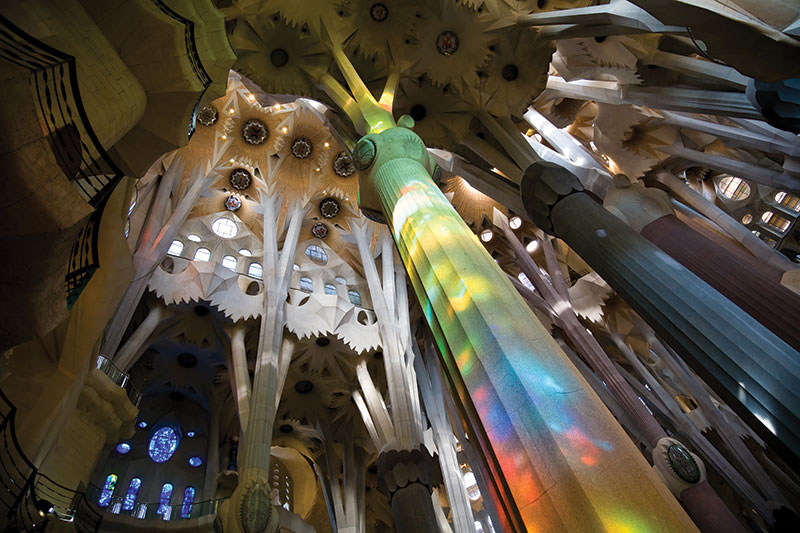
Figure 2. Sagrada Familia.
Arches
The overall forms may be the same, but the compression structure tends to be much thicker than the tension structure because it also has to resist buckling; or to put it another way, tension structures are in a stable equilibrium, but compression structures are in an unstable equilibrium. This means that if the compression structure deflects too much, it will snap, while a tension structure will adjust itself instead. In a masonry structure, where the tension capacity is minimal, buckling is prevented by keeping the line of thrust – which is the moment divided by the axial load – in the middle third of the element, thus ensuring that no part is in tension. Some masonry design guides, such as The Stone Skeleton by Jacques Heyman (1995), say that in certain circumstances the structure is fine as long as the thrust line remains within the overall section. This implies that there is considerable tension or cracking in the section, but it remains stable. The medieval builders ensured that this would happen by increasing the axial load on the buttresses by means of sculptures and pinnacles; ornamentation can be functional! (Figure 3) Reinforced concrete or steel structures on the other hand can resist this with their innate tension capacity.
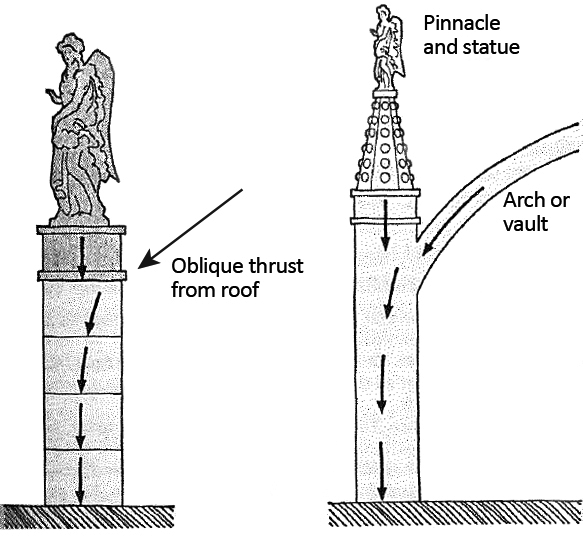
Figure 3. ©J E Gordon, Structures, or Why Things Don’t Fall Down (1978).
While flexible tension structures can readjust themselves to maintain equilibrium with the loads, masonry has much less scope to do this, but more than is commonly realized. Arches can remain stable even after the joints open as the line of arching action moves, as long as things do not move too much (Figure 4).
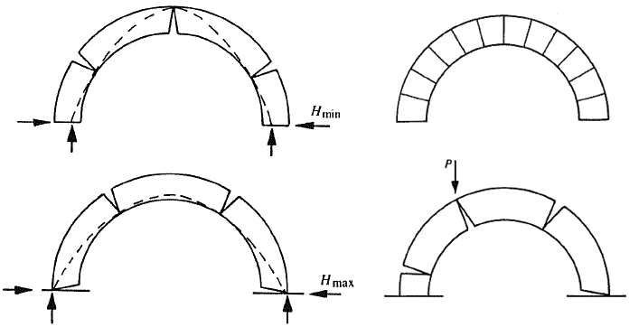
Figure 4. Thrust lines and collapse mechanism for a masonry arch (Heyman 1995).
Note that while the arch is uncracked, the centroid of resistance remains in the middle of the arch and it behaves in a linear fashion. Once it cracks, the centroid of resistance moves to the other side of the line of thrust – assuming a reasonably high stiffness – which actively resists that thrust. This illustrates a feature of many nonlinear systems; they are self-stabilizing as long as the perturbation is within certain limits.
Shells
Incredibly thin arches and shells are achievable when they are geometrically optimised, such as Robert Maillart’s 1939 Cement Hall from the Zurich National Exhibition. The door openings on the bridge indicate both the scale and the thinness of this reinforced concrete shell (Figure 5).
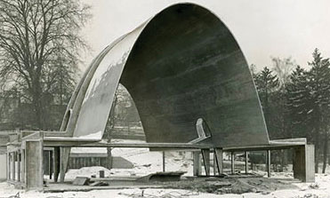
Figure 5. 1939 Cement Hall.
When the shell is constructed from a grillage or lattice, often of timber, then it is referred to as a gridshell. The nature of these structures enables very organic forms to be produced; a well-known example being the Mannheim World Garden Exhibition building (Figure 6).
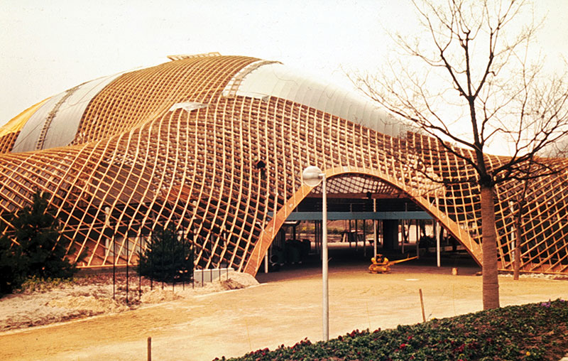
Figure 6. Mannheim World Garden Exhibition. Courtesy of Arup.
Analysis
Masonry can behave differently from other engineering materials, such as steel and concrete. It is both orthotropic and nonlinear with little tensile capacity, but finite element analysis can be very useful if employed with care.
Like all nonlinear analyses, one must remember to evaluate all load combinations together. Masonry often resists imposed loads with its self-weight, so the dead load increases the moment capacity by reducing or negating the induced tension. Also, due to its tendency to crack, the load paths through a masonry structure can vary with the applied loads and support conditions.
Consider an arch. Here one might model one-dimensional (1D) beam elements to carry the load, then use the combination of the bending moments and axial loads to check that the eccentricity is within limits. Some programs include this calculation in the post-processor, possibly described as Thrust or Torce lines. If the Torce line remains within the middle third of the section, then no tension is induced (Figure 7). One can improve the behavior of the arch through geometric optimization, also known as form-finding, which will be discussed below.
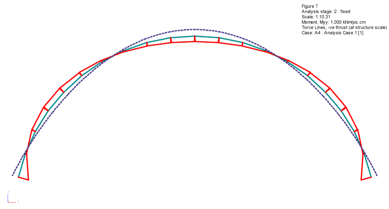
Figure 7. Circular arch.
Like many nonlinear structures, the load path through cracked masonry will change with the load and movement. One can model this within an arch by using two-dimensional (2D) elements and what are known as “flip-flap” joints – compression-only strut elements – in the arrangement shown in (Figure 8). Like all masonry analyses, it is important to model the support stiffness accurately, as this has a major effect on the end result.
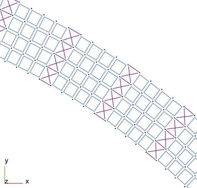
Figure 8. Flip-Flap arch analysis.
For more complex models, such as a cross-section through Westminster Abbey (Figure 9), you can use a full 2D mesh to analyze the lines of principal force, shown here in green for compression and red for tension. This analysis assumes that the masonry is uncracked, so is only suitable if the stresses remain low. You can get a good idea of the line of thrust from the flows of compression lines, as well as locations of likely cracking (Figure 10).
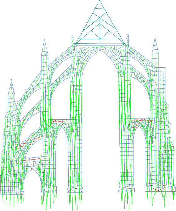
Figure 9. GSA model of Westminster Abbey.
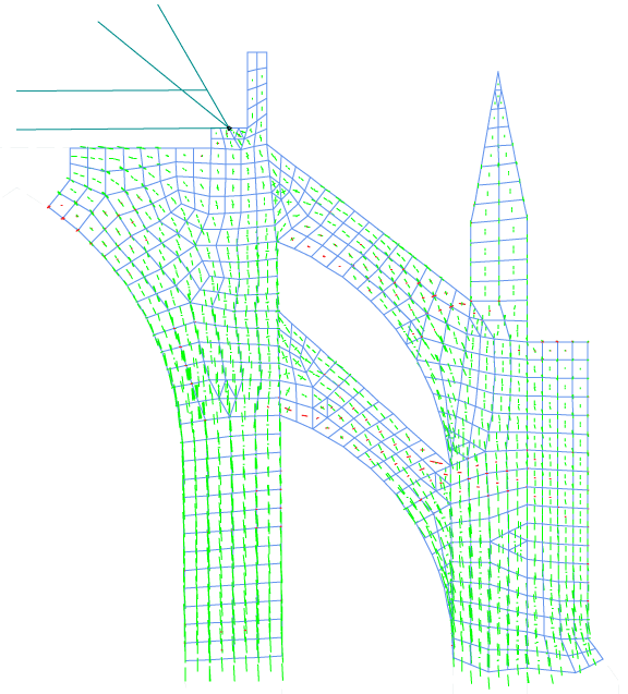
Figure 10. Thrust lines from FEA principal stresses.
Form Finding
Physical models are still incredibly useful, at least for the initial design, as they are very quick to give results in a form that is tangible. The author has personally found physical models especially useful for tensegrity structures. Physical models have the limitation, though, that they are difficult to take measurements off and very poor for quantitative analysis. The good news is that there are now a number of computational methods available to determine the geometry such that the model can be analyzed. Note that these methods are called “form-finding,” as they are searching for the optimum form, not calculating it; this means that they can sometimes get lost on their journey, and might need guiding to the desired result.
A close look reveals that the Sagrada Familia (Figure 2) is essentially the same as that of Cement Hall, which is the form of a parabola, the ideal shape for an arch under uniform load. This shape was determined in the 17th century by Robert Hooke, who realized that the perfect arch exactly mirrors the catenary shape of a hanging chain.
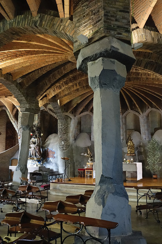
Figure 11. Colònia Güell Crypt.
Gaudi made use of this phenomenon when designing his cathedrals (Figure 11). He determined the overall form by modeling the columns and arches with chains and superimposed loads with weights (Figure 12).
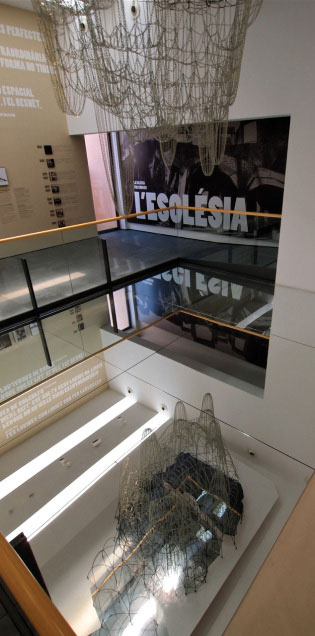
Figure 12. Antonio Gaudi’s hanging chain.
Frei Otto used physical models for the Munich Olympic structures prior to numerical analysis. Another famous example is the gridshell for the Mannheim World Garden Exhibition by Ted Happold and Ian Liddell while they were at Arup, prior to their forming of Buro Happold.
Creating a model for form-finding requires first establishing the boundary conditions, which are the fixed points, as well as any fabric edges, which need either a flexible pretensioned cable or solid member to pull them taut. The engineer must also decide on the form-finding properties and loads that will push or pull the model into shape. These will vary depending on the selected form-finding method; some might be calculated, and some be an initial guess.
Force Density Form-Finding
Force Density is one of the earliest and quickest of the numerical form-finding methods, but it is a little abstract. A 2D element’s area is set proportional to its stress, and a bar element’s length is set proportional to its force. This means that a longer element will have a reduced force density, and vice-versa (Figure 13).
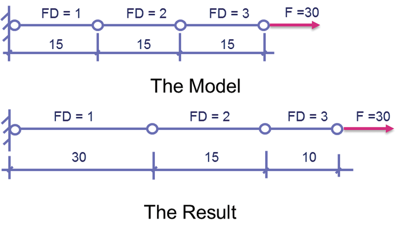
Figure 13. Force Density form-finding.
The end result should not only be a balanced geometry, but also a set of forces that may need to be scaled to the desired pretension values.
Force Density is a quick way to get results, but it may require some experimentation to get the desired form. It is quite good for cable nets, but not as good for fabric structures as there cannot be different prestresses in the two orthogonal directions, restricting the forms that can be achieved.
Soap Film Form-Finding
The Soap Film method of form-finding replicates the minimum surface inclinations of soap bubbles, by replacing the 1D bars and 2D fabric elements with elements that have a constant stress but zero stiffness. Conceptually, this is similar to soap bubbles edged by elastic bands.
Because there is no stiffness in the system, apart from restraint points and beam elements, the nodes are free to move anywhere and so can possibly get in a muddle. This requires the addition of form-finding elements called Spacers that are there just to ensure that the nodes are equally spaced out.
While the method requires more work than Force Density, the major advantage of Soap Film is that it specifies the target prestresses rather than the more arbitrary force per length or area, and thus provides a more logical control over the final form, as well as probably resulting in a structure with less material.
Another advantage of Soap Film over Force Density when using certain form-finding programs is that one can specify different warp and fill (weft) prestresses, which is extremely useful for conic fabric structures, as they generally need a relatively higher radial prestress, and can be beneficial for other forms as well.
Normal Properties Form-Finding
Normal Properties form-finding literally uses the normal properties of the elements. This means changing the structural geometry to the deflected shape, rather than just determining how the given structure will deflect, with the possible option of locking in the resulting forces and distortions. This means that it is both an excellent method for form-finding grid shells, replicating a hanging chain physical model, and for determining locked-in stresses from construction sequencing.
As an example, Buro Happold’s London 2012 Olympic Main Stadium design used Normal Properties form-finding to analyse the locked-in construction stresses in the compression ring, and then Soap Film form-finding for the roof cables and infill fabrics.
Conclusion
Compression structures may not be the most obvious candidates for lightweight options, but whether tensile or compressive, lightweight structures can soar over space to create iconic and efficient buildings. It is just a matter of getting the shape right.▪