
The New York City stock of retaining walls is dominated by concrete and masonry walls. The older stock, dating from late 1800s and early 1900s, consists of stone masonry walls. Originally, these soil retaining structures were mostly commissioned and supervised by public works, parks, railway or highway administrations. In the early 1900s, under pressure from strong residential needs, the city started to open streets in hilly areas that previously had not been considered suitable for construction. Private development ensued and developers began to erect stone retaining walls to meet street lines or to create terraces around their properties.
A recent New York City local law requires periodic inspection of walls that are taller than ten feet and that front a right of way. The professional performing the condition assessment of old stone walls needs to be capable of recognizing symptoms of distress while being aware of the regulatory and design criteria as well as of the construction methods that formed the retaining wall practice at the time these walls were erected. This article provides a general overview of the issues related to the assessment of old stone retaining walls existing in New York City. Most of the symptoms of deterioration discussed were observed during the New York City Building Department’s inspections and filtered through the experience of several forensic collapse investigations (See Figures 2, 5 and 6).
Construction
Modern engineering systems classify old masonry walls as “gravity walls”, as their stability is provided by their weight. At the time they were built, the classification was based on the type of stone used for their exposed face – ashlar and rough. Ashlar, built with stone precisely cut, represented the higher “class” of wall construction in contrast to the rough (or rubble) walls that were built with stone that was not cut or not cut at right angles.
The retaining walls were usually erected in lifts and started with the regular masonry face behind which lesser quality stone was deposited or dumped. Like in any multi-wythe bearing walls, headers (through-stones) were necessary to connect the vertical wythes. The mason’s skill consisted of selecting each stone so that it fit with the adjoining stones. Walls built without mortar or any other binding layer are called dry walls. In the absence of mortar, the gaps between stones were filled with smaller stones called pins. The pins were also used to hold the larger stones in desired positions. High quality stone dry wall construction possessed significant stone-to-stone contact. Some stone walls, most likely built after World War I, were stabilized with anchor rods and, as such, are not gravity walls. The importance of water drainage and of the type and mode of backfill has been recognized since the earlier periods.
Building Code Regulation
The first city building code instructions involved only basement walls that were intended to retain soil. The first ordinance to cover any structure retaining soil was issued in 1915 and was incorporated in the 1916 code. Retaining walls were required to be “so designed that in resisting the pressures to which they are subjected, including any water pressure that may exist, the working stresses of the materials shall not be exceeded, the soil shall not be overloaded and the stability of the wall shall be insured.”
This text remained until 1938, when the code was changed to provide engineering design instructions only for basement walls.
The first explicit factor of safety of 1.5 for overturning and sliding was set in the 1968 Code, matching the widely recognized Design Manual: NAVFAC DM-2 Dec. 1967. This factor of safety value has remained in the code since. In 1995, the code was amended to include seismic loads on retaining walls.
Design Criteria
Because original construction records rarely exist, it is unlikely that an engineer performing a condition assessment of a particular wall would know which design method was used. Of course, the fact that a wall has survived decades is proof of the reliability of the original design, but sometimes, without an in-depth analysis, it may be difficult to establish whether an observed deterioration is an indication that the structure is reaching the limits of its safe life.
Around 1890, J. Trautwine, arguing that “experience, rather than theory must be our guide”, published empirical guides for proportioning retaining walls. These guides seem to have been widely followed.
Trying to make sense of the numerous theories of retaining wall design in his Treatise of Masonry Construction (1899), Ira Baker found only three reliable theories (Coulomb’s, Rankine’s and Weyrauch’s theories) and two empirical rules (English by Benjamin Baker and Trautwine’s rules).
Ira Baker enumerates the following “methods of failure”: ”(1) By revolving about the front of any horizontal joint, or (2) by sliding on the plane of any horizontal joint, or (3) by the bulging of the body of masonry.” Developed around the same period, the classification of failures into overturning, crushing and sliding was more helpful, as it could be used as a guide to design. Friction and compressive strength of the wall material or of the underlying soil could be evaluated and compared with limits determined by testing. By and large, these modes of failure are still basic considerations in modern gravity wall designs. General soil slope stability became a recognized mode of failure after 1920.
The 1920 G. Paaswell’s overview of contemporary design methods shows that most had embraced Rankine’s and Coulomb’s theories. Paaswell reports that the calculation methods produced various overturning factors of safety, all higher than 2.5. In his view, the attention paid to overturning was exaggerated since most retaining walls collapsed due to underlying soil failures and rarely in overturning. He favored graphic design methods that better predicted pressures on soil, as they forced the resultant to be in the middle third of the base.
In short, most of New York’s stone masonry walls were erected during the period when designs evolved from empirical methods to quasi-modern design theories. Concrete retaining walls started to be built around World War I. Not uncommon in New York City are walls with stone or brick veneer with concrete backup stem walls. They were built after 1940 and are assessed as concrete (flexible) walls.
Visual Assessment
Intended for the National Park Service, the Retaining Wall Inventory and Condition Assessment Program ( WIP) recommends that assessments of old walls be guided by visual observations and also take into consideration determinations whether the wall “is consistent with other structures of its type and period of construction exhibiting established construction workmanship and good performance,”
Casting some doubts on the effectiveness of visual inspections Y. C. Chan reports, in his Study of Old Masonry Retaining Walls in Hong Kong, several cases of walls that collapsed without forewarning signs. This is not New York City’s forensic experience, but one can envision cases where walls in good condition were overwhelmed by newly applied forces that exceeded the original design.
Any aging stone facade may show signs of deterioration, i.e. delamination, peeling, erosion, loss of mortar, unit cracking, etc. A visual assessment of a stone retaining wall needs to differentiate between such symptoms of aging and those that indicate the possibility of a more severe failure or accident. For instance, some cracks, commonly found in the vicinity of corners, are just the result of deformations due to thermal movement. Such expansion cracks, even when they completely separate the wall into two segments, might not affect the wall’s stability, as each segment may remain capable of resisting the out of plane forces acting upon it (Figure 1).
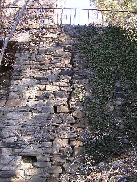
Figure 1. Crack in rubble wall.
Outward lean of a wall is a significant symptom presaging collapse (Figure 2). It may be caused by insufficient or deteriorating strength or by the failure of the soil underlying the toe. In the absence of original drawings, it is difficult to ascertain whether the present orientation of the wall face matches the original intended geometry. (e.g., did the wall move from an original batter?). Over a long period of time and as a result of intermittent load increases (e.g., high rainy seasons and icing pressures at the top) and simultaneous reduction of friction, the wall might have slowly moved from the original vertical or battered position, thus reducing the original factor of safety. It is conceivable that the outward displacement of a wall might decrease the pressure of the retained soil (i.e. from at rest pressure to active pressure). A new equilibrium is then reached, but again, this might be disturbed by subsequent events (e.g., high rainy seasons) capable of increasing the pressure.
Figure 2. Retaining wall stabilized with rakers after collapse. Note lean of wall.
Outward rotation or movement of a wall has associated signs of distress that include sink holes and tension cracks at or around the top of the wall. Sometimes sink holes may only indicate erosion of the retained soil. At the bottom of the wall, one might observe soil swelling and sloping towards the wall. For long stretching walls, observation of the alignment at the top of the wall can indicate differential movement of wall segments. It might also help distinguish walls built with batter from wall segments that moved (Figure 3).

Figure 3. Irregular alignment at top of wall.
Incipient sliding failure at the base may be preceded by swelling of soil at the bottom of the wall. In some cases, there is a separation of soil at the top of the wall. Sliding of portions of the wall along intermediate planes can lead to outward deformation of the top of the wall or bulging at the lower parts of the wall. Sliding of the top of the wall may lead to collapse of this top portion (Figure 4).
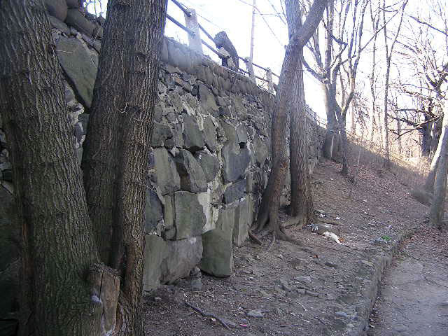
Figure 4. Bulging wall.
When bulging is local, one could assume that it is due to some construction deficiency like an improperly pinned or placed stone. But bulging on larger areas is a sign of crushing and sliding due to stresses concentrating towards the outside edge of the wall. Bulging can also be caused by insufficient ties between wythes.
Even when the aspect of the outside face is satisfactory, there remains significant uncertainty as to the method of construction used for each particular wall (Figure 5).
Figure 5. A visual inspection prior to collapse might not have detected that the wall was only 2 feet deep.
Increase in Load
Unlike other structures, a retaining wall is exposed to most of the design loads as soon as it is built. One could assume that, over the long period since a wall’s erection, the high and continuous loads have already produced the collapse of poorly constructed or designed walls. Assessment of indications of changes potentially leading to an increase in loading conditions is essential. Change in grading, demolition or construction of a nearby building can be significant sources of new or increased loading (e.g., new pressures on soil or changes in water flow patterns.)
An effective assessment needs to include the entire system of rain water management, as water accumulation behind the wall can produce a significant load increase. Many wall collapses have been associated with heavy rainfalls. Usually, when provided with drains and weep holes, walls need not be designed to resist water pressure. But the drains can deteriorate or get clogged. Fines transported from elsewhere might reduce the drainage capacity of the crushed stone layer intended to allow water circulation. New grading of areas, or of streets at tops of walls, may change the distribution of rain water.
Significant vegetation growth on the face of a mortared stone wall could be a sign of continuous water presence due to a lack of sufficient drainage. Water leaking through joints or cracks is a sign of a drainage system malfunction.
Dry stone walls generally allow water to circulate, except for cases when subsequent repairs added mortar to the face of the wall (Figure 6). Ice formation or tree roots might create “wedges” that could lead to some local wall deterioration.
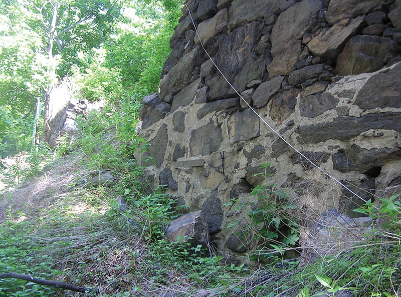
Figure 6. Collapsed dry wall. Repair pointing at the base, intended to keep pins in place, might have contributed to collapse.
Detailed Assessment
The condition assessment needs to correlate the various symptoms observed and to integrate them into a final evaluation that indicates the safety risk, if any, posed by the retaining wall in its totality or posed by individual elements. In some cases, uncertainty about the wall condition will require a detailed engineering investigation. Exploratory probes and tests can reduce by a significant amount the uncertainty regarding data to be used in calculations (wall profile, position and inclination of back side, characteristics of backfill, specific weight of the wall itself, engineering properties of mortar, depth of wall foundation and capacity of underlying material, etc.). Often, the confidence of the assessment can be improved by the use of a sensitivity analysis, a method that helps establish by what degree an uncertain result (e.g. overturning factor of safety) is dependent of the variation of an uncertain input (e.g. weight of wall, backfill density or soil friction, etc.)
Evaluation
The large number of uncertainties that make assessments of old stone walls difficult should not necessarily lead to the conclusion that these walls are inherently unsafe. The evaluation should take into consideration all observations of individual symptoms, and consider their cumulative effects as well as their relationship to each other and to the wall’s structure. In some cases, the engineering opinion might need to be supported by probes and engineering calculations.▪
References
Naval Facilities Engineering Command (1967) Design Manual: Structural Engineering: NAVFAC DM-2 Dec. 1967 Department of the Navy
Trautwine, J., (1886) The Civil Engineer’s Pocket-Book – Revised, New York, John Wiley
Baker, Ira, (1905) A Treatise of Masonry Construction, 9th ed. New York, John Wiley
Paaswell, G., (1920) Retaining Walls: Their Design and Construction, New York, McGraw Hill
FHWA-CFL/TD-10-003 (2010) Retaining Wall Inventory and Condition Assessment Program ( WIP) National Park Service Procedures Manual, Lakewood, CO
Chan, Y C (1996). Study of Old Masonry Retaining Walls in Hong Kong. Geo Report No 31. Hong Kong: Geotechnical Engineering Office
Brady K. C., Kavanagh, J. (2002) Analysis of the Stability of Masonry-faced Earth Retaining Walls, Transport Research Laboratory (Great Britain), Transport Research Foundation (Great Britain)
New York State Department of Transportation, (2014) Bridge Inspection Manual
Federal Highway Administration, (2012) Bridge Inspector’s Reference Manual FHWA NHI 12-049