
When it comes to enclosing large building volumes, it is hard to beat tilt-up concrete construction for economy and durability. Long considered the mainstay for warehouses and big-box retail, the tilt-up method is now frequently employed for commercial projects, churches, schools and Class A office buildings nationwide. With newer types of occupancies driving attention to aesthetics higher and higher, the importance of minimizing concrete cracking in the site-cast precast wall panels is greater than ever.
Tilt-up concrete construction incorporates concrete wall panels that are formed, cast and cured on a ground supported slab at the building site and then tilted into place, one large panel at a time. The individual wall panels are erected around the building’s perimeter, separated by vertical joints. Single story occupancies are still most common; however, many buildings are now multiple stories. While many of the features of tilt-up panel construction tend to reduce the potential for developing cracks when compared to conventional concrete construction, the unique method of how the buildings are constructed still requires some special considerations for controlling cracking. The lifting and setting of wall panels, as well as the effects of restrained drying shrinkage, are important items to address to minimize potential wall cracking.
Construction Related Cracking
In some respects, the concrete wall panels experience the greatest potential for cracking as they are being tilted from horizontal to vertical while being erected. As the panel is lifted from the casting slab, over 1g of force can develop normal to the wall’s surface due to dynamic forces or bonding to the casting slab. These bond forces can develop from an inadequate application of the bond breaker coating on the casting slab, or excessive rain water left standing in the panel openings and reveals without an adequate side draft on at least one edge. As a precaution, the bond breaker application should always be checked just prior to casting the panels. Excessive bending stresses can result in horizontal or vertical cracks aligned at architectural reveals or edges of openings. However, with the use of adequate safety factors, properly located lift-points and appropriate rigging, the out-of-plane bending moments generated during lifting can usually be reduced to acceptable levels to minimize the potential for cracking. If the panel can’t be lifted with an adequate factor of safety, additional measures can be employed as presented later in this article.
To successfully lift the panels for most of the tilt-up projects designed and built today, the use of sophisticated computer software to analyze the stresses generated in the panels during lifting is required. A specialty lifting engineer, often associated with the tilt-up accessory vendor, who has the required expertise and experience, most often provides this service. Typically, the panel designer will not provide the analysis and design required for lifting the panels. However a general understanding of the lift engineering process will help in designing panels that can be erected economically with minimum potential for cracking during construction.
Ideally, the tilt-up panels can be erected without developing any cracks during the lifting process. Therefore, the panels are typically designed using only the allowable flexural tension strength of the uncracked panel section without relying on the steel reinforcement. The calculated bending stresses within the panel are kept low enough so that cracking should not occur. The minimum concrete flexural strength required prior to lifting the panels is specified by the specialty lifting engineer to provide an adequate factor of safety of about 1.67 against cracking. For most projects, a minimum compressive strength of 2,500 psi with a corresponding allowable flexural stress of 300 psi (typically calculated as 6 [pmath]sqrt{f}prime_{c}[/pmath]) is specified by the specialty lifting engineer and is considered the minimum requirement prior to lifting the panels.
If the calculated flexural tension stress exceeds the specified minimum allowable due to large panel openings or reduced sections at reveals or recesses, a higher strength concrete can be specified for those panels to increase the allowable flexural stress in order to maintain an adequate factor of safety against cracking. When the concrete strength is increased, the panel reinforcing should be checked to verify that φMn ≥ Mcr is still satisfied as required by ACI 318. Another approach often used is to design the lifting stresses closer to the ultimate plain concrete flexural stress (sometimes calculated as high as 10 [pmath]sqrt{f}prime_{c}[/pmath]) with less margin against cracking, and provide redundant steel reinforcement to resist the entire calculated bending moment should cracking occur. Many times, when the as-designed structural reinforcing is accounted for, no or only a few extra reinforcing bars are necessary to be added to the engineered wall design. When reinforcing is added for lifting, the section should be checked to verify that it is not over-reinforced, creating a compression controlled critical section.
In some panels with extremely large or unusual openings, external strong-backs will have to be added temporarily to the panel to resist the calculated bending moments and stiffen the panel sufficiently in order to keep the concrete flexural stresses below the estimated cracking strength of the section. The use of strong-backs add time and expense to the project. Many times slightly increasing the thickness of the panels can eliminate the need for strong-backs and actually reduce the cost of the project. Simply adding reinforcing steel has limited effectiveness, especially because the steel remains primarily dormant until the concrete cracks.
Drying Shrinkage Cracking
The Engineer-of-Record (EOR) for a building typically has limited involvement in the means and methods of rigging and lifting a panel during construction, and the related cracking that could occur. However, the EOR often has more control to address potential cracks associated with concrete drying shrinkage.
Cracking in tilt-up wall panels can occur when excessive restraint prevents the movement from horizontal drying shrinkage. Drying shrinkage naturally occurs as water exits the concrete material, and can become a significant consideration depending upon several factors. Fortunately, vertical panel joints that are free of panel-to-panel connections inherently provide strain relief for the horizontal concrete shrinkage; however, diaphragm chord connections at the roof and floors, and foundation and slab connections, create unintentional restraint. Greater panel widths have greater horizontal shrinkage potential, so limiting widths where possible is recommended. Panel widths between 20 and 30 feet are most common.
When welded panel-to-panel connections occur, isolated embedded plates and anchors near the panel joints could suffer a concrete breakout failure unless sufficient reinforcing steel is utilized to develop the resulting forces deeper into the concrete. Figure 1 illustrates a panel-to-panel connection with bolts in horizontal slotted holes to accommodate the horizontal movement; however, the plate was inadvertently welded on both sides, creating horizontal restraint. Tilt-up designers often avoid welding a large series of panels together across the panel joint to minimize this problem. Roof and floor chord connections are an exception.
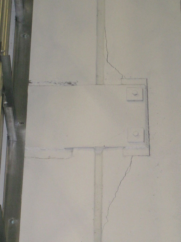
Figure 1. Panel to panel connector plate designed with bolts and slotted holes to accommodate panel shrinkage and temperature movements, inadvertently welded on both sides of the joint.
At the roof and floor chords, welded connections are common, but the use of horizontally slotted bolt holes near the panel joints in rolled steel ledger sections minimizes the restraint to horizontal shrinkage near the vulnerable panel joint edge. Additionally, some engineers specify a delay in welding the panels together across the joint until roof erection is well underway to allow a larger percentage of the ultimate horizontal shrinkage to occur, and allow the concrete strength to increase, prior to welded restraint. The best solution is to keep restrained panel-to-panel connections well away from panel joints.
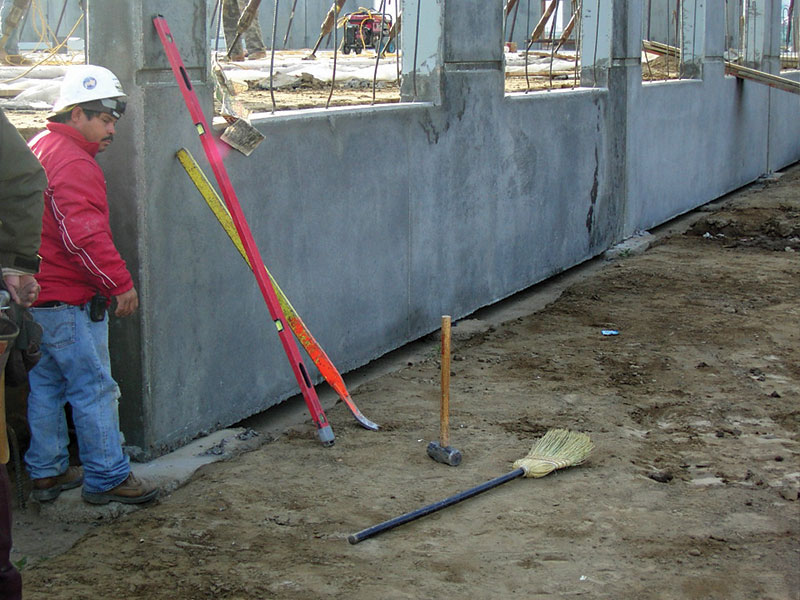
Figure 2. Grout setting pads at panel joints with an inactive shim at the panel center.
One of the more aggravating cracking patterns is caused by base restraint due to long term drying shrinkage. When the wall panels are erected, they are normally placed on two 1-inch to 2-inch thick grout setting pads placed on the foundation, and the frictional restraint at this bearing condition may have significant resistance to the horizontal shrinkage (Figure 2). The resulting tensile forces can combine with the vertical shear forces to result in a cracking pattern of several radiating cracks in the lower quarter of the panel’s height (Figures 3 and 4). Ideally these setting pads are hard plastic shim packs instead of grout pads, thus minimizing the frictional restraint to horizontal in-plane shrinkage. Situations where contractors use a single grout setting pad at the panel joints (Figure 2) have been especially problematic. For contractors who insist on using grout setting pads, the potential for developing these cracks can be minimized by providing independent setting pads away from the panel joint instead of a single common setting pad, thus reducing the amount of shrinkage strain between the friction restraints as well as reducing the interacting vertical shear at the pad support.
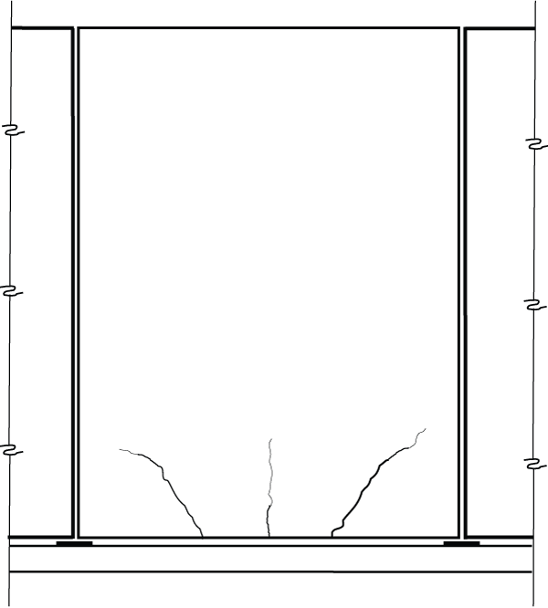
Figure 3. Potential crack pattern associated with setting pads and other base restraint conditions.
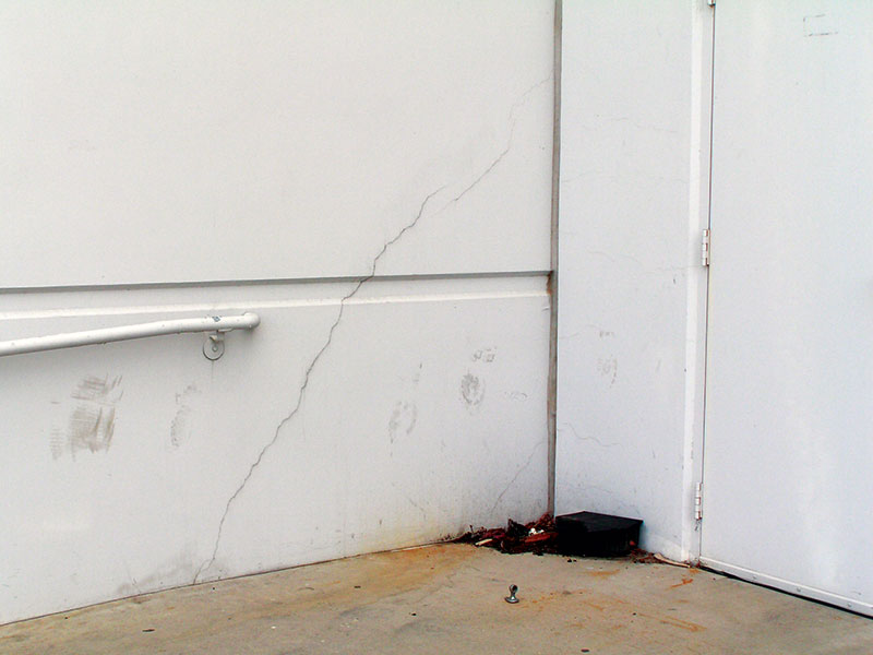
Figure 4. Cracking associated with base restraint.
Similar restraint issues can occur after the joint below the panel is grouted, or if panels are immediately connected to foundations and/or the slab-on-grade. By delaying connections to the footing or slab and allowing a larger percentage of the ultimate drying shrinkage to occur, while also allowing the concrete strength to increase, the likelihood of developing these cracks is reduced.
Many of the solutions discussed so far deal with minimizing the restraint or resisting it with reinforcing steel. It is also helpful to encourage much of the drying shrinkage to occur prior to any connection or restraint forming. For example, extending the time between when the concrete panel is cast and lifting it into place allows the concrete’s tensile strength to increase and allows a larger portion of the ultimate shrinkage to occur. Typically panels are lifted within two weeks of casting. Use of proper curing techniques also allows a rise in concrete tensile strength while slowing down drying shrinkage.
The amount of shrinkage expected in the concrete can also be reduced by controlling the amount of water necessary in the mix, and/or increasing the amount of coarse aggregate without causing honeycombing or voids, and/or other techniques such as shrinkage reducing admixtures.
It is not practical to expect all restraint to be eliminated, and it may be prudent to provide additional reinforcing to limit crack widths. In many parts of North America, the tilt-up wall panels are placed on cementitious grout pads on top of the foundation, with the resulting joint subsequently grouted, and the only positive connection occurring at the floor slab at some later date during construction. In this situation, providing enough reinforcing steel to withstand the calculated restraint force may be an appropriate course of action to consider, as is demonstrated in the following example:
Panel thickness = 8 inches
Service gravity load acting at base of panel, PTOTAL = 110 kips
Factored gravity load acting at base of panel Pu TOTAL = 150 kips
Factored gravity load acting on each grout pad support Pu = 0.5Pu TOTAL = 75 kips
Estimated coefficient of friction between panel and pad µ = 0.6 (ACI 318-11 Section 11.6.4.3)
Maximum horizontal self-straining shrinkage force Tu = µPu = 0.6(75 kips) = 45 kips
Recommended Grade 60 reinforcing steel area:
As =(45 kips)/(0.9(60 ksi)) = 0.83 in2; Use (3) #5 horizontal bars at base of wall (As = 0.93in2)
Service load steel stress, fs = (110/2) 0.6 / 0.93 = 35.5 ksi < 40 ksi (ok)
Check the maximum clear cover cc on reinforcing provided, per ACI 318-11 Section 10.6.4:
s = 15(40,000/35,500) – 2.5 cc with s = panel thickness = 8 inches and solving for maximum cc, where cc is the distance from the bottom of the panel to the surface of the reinforcement.
cc = (15(40,000/35,500) – 8)/2.5 = 3.6 inches
Place the first bar at 3 inches from bottom of panel; cc provided = (3 – 0.625/2) = 2.7 inches < 3.6 inches (ok)
Situations where additional restraint is present, such as panel to footing connections and connections to the floor slab not delayed sufficiently, will have higher self-straining loads Tu and can be addressed in a similar fashion.
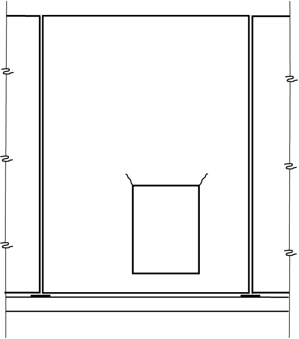
Figure 5. Potential corner cracks at wall penetrations from drying shrinkage.
Well above the panel’s base, diagonal cracks emanating from the corners of window or door openings can occur (Figure 5) due to stress concentrations from long term drying shrinkage at these re-entrant corners. The use of two No. 5 x 4-foot reinforcing bars centered diagonally at the opening corners in addition to the No. 5 bars required by ACI 318-11 Section 14.3.7 (Figure 6) have been successful, keeping the crack size reasonably tight.
Figure 6. Diagonal corner bars to control cracking.
Conclusion
In closing, the nature of tilt-up concrete construction using individual panels with largely unrestrained panel joints is a great asset to controlling cracking. With greater performance demands, driven by developers and owners, more and more effort is placed on controlling all cracking potential in tilt-up panels. Because the engineer’s panel design significantly affects a tilt-up project’s constructability, best practices are when the building’s design engineer and contractor’s lifting engineer freely communicate about the difficult portions of the project before construction commences. Whether a simple warehouse or a five-story class A office building, understanding the mechanisms that lead to possible cracks and addressing them at both the design level and construction level will be of great benefit to a successful finished project.▪
Additional Resources
Engineering Tilt-Up, Timothy Mays & Joe Steinbicker, Tilt-Up Concrete Association, 2013.
The Construction of Tilt-Up, the Tilt-Up Concrete Association, 2011.
Design Guide for Tilt-Up Concrete Structures (ACI 551.2R-10), American Concrete Institute, 2010.
Tilt-Up Concrete Construction Guide (ACI 551.1R-05), American Concrete Institute, 2005.