
Historic Bush Terminal Complex, Brooklyn, New York
Industry City in Brooklyn, New York retained Pennoni Associates, Inc. (Pennoni) to complete an evaluation of the existing roof structures at Buildings 2, 3, 5, 9, 10, 19, 20 and 26 of the historic Bush Terminal Complex (Figure 1). The primary purpose of this effort was to determine the load-carrying capacity for new “green” roofing systems, solar panel arrays and other adaptive reuse proposals.
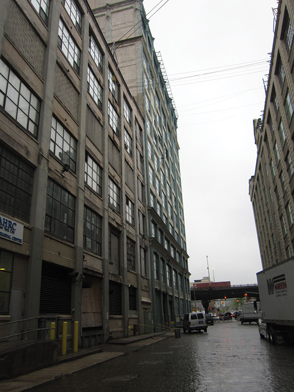
Figure 1.
Due to the lack of original structural drawings, it was necessary to field-determine the internal reinforcement of the concrete system at a typical bay in each building. This involved creating small inspection openings to expose the reinforcement at areas of the framing where removing insignificant amounts of concrete material would not compromise structural integrity (Figure 2). This approach, used in conjunction with a Profometer (or Pachometer), enabled the determination of the existing reinforcing in the immediate area surrounding the exploratory openings.
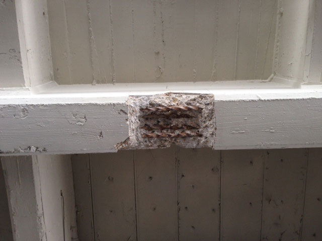
Figure 2.
Pullman Shared Systems Technology, Inc. (Pullman), as a sub-contractor to Pennoni, performed the exploratory demolition; WJE, as a sub-consultant to Pennoni, conducted the Profometer readings. The approximate concrete compressive strength was obtained by using a Schmidt (or Impact) Hammer in the same vicinity.
History and Description of the Buildings
The buildings in the Industry City complex were constructed between 1904 and 1911, and were originally referred to as the Bush Terminal Company facility. A search of available historical records revealed that the architect, engineer and contractor, for most if not all of the buildings, were William Higginson, E.P. Goodrich and Turner Construction Company, respectively. Additional history of the site can be found at http://industrycity.com/history/
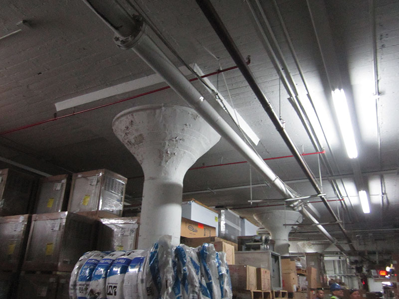
Figure 3.
All of the buildings associated with the investigation were constructed as conventionally reinforced, cast-in-place concrete structures. Building 26 was constructed as a two-way flat slab with drop panels and column capitals, which were all supported by round concrete columns (Figure 3). All of the other buildings were framed as one-way slabs, joists and beams, which were supported by either round or square concrete columns (Figures 4 and 5). The buildings varied in height from six to twelve stories, not including basements.

Figure 4.
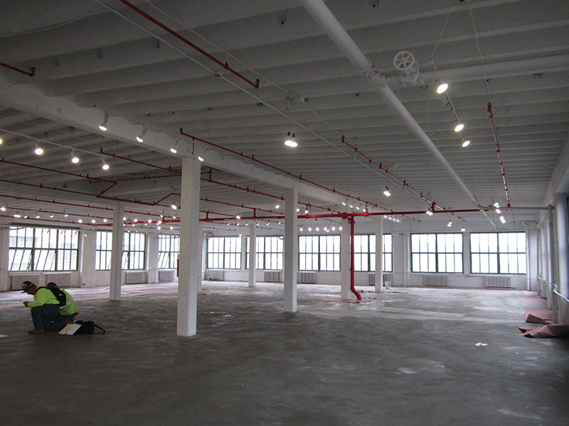
Figure 5.
In general, the existing roof structures were in good condition, with painted soffits, and supported suspended loads such as lighting/electrical, sprinklers and piping, as well as rooftop loads such as steel piping, electrical power lines and small mechanical equipment. The roofs also included skylight openings, most of which that had been removed and enclosed with supplemental framing (Figure 6).
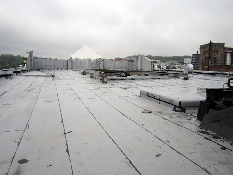
Figure 6.
The roofing systems at all of the buildings, except for Building 2 (which had been recently reroofed), were in very poor condition, which was confirmed via roofing cores that were obtained by Pullman. The primary purpose of the roofing cores was to determine the weight of the existing roofing systems, which varied between 1.0 and 6.0 psf.
Analysis and Material Testing
The assumed strength of the reinforcing bars was based on information provided in an out-of-print book entitled Reinforced Concrete in Factory Construction, published in 1907. This publication included an entire chapter dedicated to the design and construction of Building 2 and indicated that the floor live load was 200 psf. Additional research of other historical publications, including the 1911 edition of The American Architect magazine, indicated that the six-story buildings at the complex were designed for a floor live load of 150 to 400 psf and a roof live load of 75 psf.
Because of the limited access available to the top flexural reinforcing in the slab, joists and beams, the analysis of these members was based on the positive moment capacity of the sections determined from the exposed bottom flexural reinforcing at the exploratory openings located at the soffit and midspan of the selected typical members. The assumed dead loads included the self-weight of the framing, the weight of the roofing system and an additional 3.0 psf to account for miscellaneous suspended mechanical loads. The minimum roof snow load, based on the governing building code, was 20 psf.
The results of the initial analysis and report indicated that, in some cases, the reserve load-carrying capacity of the existing roofs under investigation was considerably less than the 70 psf load capacity documented in the available historical references. As a result of this initial conclusion, which was based on a tensile strength, ft, of the reinforcing bars of 16 ksi as documented in the same historical references, and in conjunction with the proposed use of the roofs as public assembly space with a live load of 100 psf, Pennoni recommended material testing of the reinforcing bars.
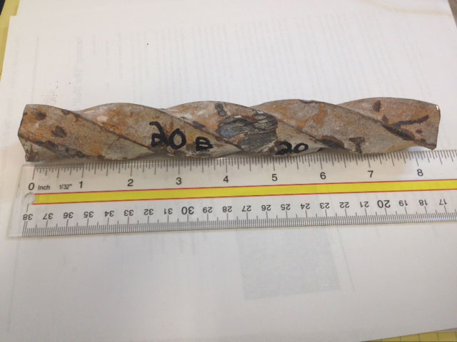
Figure 7.
Samples of the bottom flexural reinforcing of the same roof joists that had previously been subjected to exploratory demolition were obtained at the end of the members immediately adjacent to the supporting beams (Figure 7). An additional similar sample from a beam was also obtained from Building 20 at the end of the member immediately adjacent to the supporting column. The bottom flexural reinforcing sample from the flat slab in Building 26 was removed immediately adjacent to a drop panel. A reinforcing steel sample could not be obtained in Building 9 because of limited access and the lack of bottom reinforcement in the available redundant areas of the joist investigation.
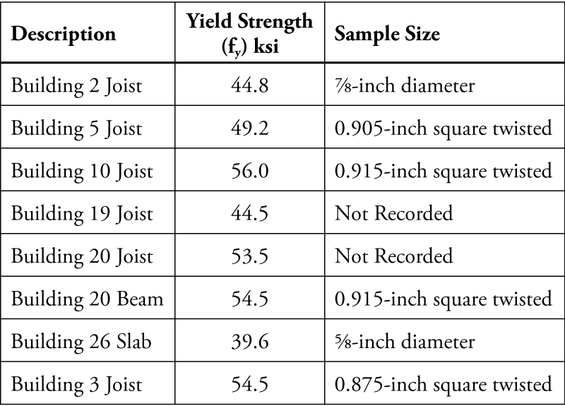
Table 1.
The samples were exposed using similar exploratory demolition methods with 6- to 8-inch-long samples of the reinforcing steel removed and sent to a laboratory for testing. The damaged area of the remaining reinforcing steel was not repaired, because the samples were obtained from an area of the member in which there was no positive moment, therefore the presence of the bottom flexural reinforcement was redundant. Table 1 summarizes the test results.
The results of the material tests indicated that the actual yield strength (fy) of the reinforcing bars varied from 39.6 ksi to 56.0 ksi. This magnitude of strength is considerably greater than the previously known highest grade of vintage reinforcing steel documented by the Concrete Reinforcing Steel Instituting (CRSI) that was in use at the time, which was Grade 30 (fy = 30 ksi; ft = 16 ksi). CRSI confirmed that the use of reinforcing steel as high as Grade 40 to 56 in the first decade of the 1900s at these buildings is an anomaly from previous historical records for the same era.
Reanalyzing the roof framing, based on the actual yield strength per the material testing, resulted in a considerable increase in the Maximum Allowable Reserve Load Capacity noted in Table 2. These values already account for the self-weight of the structure, the miscellaneous mechanical superimposed dead load, the dead load of the existing roofing system and snow load. With the exception of Building 26, and as indicated in Table 2 for Building 20, the results are based on the joist capacities, which were always less than that provided by the beams.
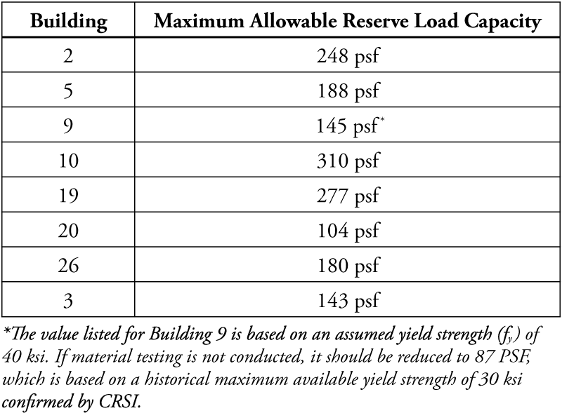
Table 2.
In general, it appeared that most of the roofs, except for Buildings 3 and 20, were designed and constructed for approximately the same floor live load of 200 psf as documented in the historical records. It is also not unusual to be able to justify a higher live load capacity than that intended by the original design by using current ultimate strength methods, rather than the working stress methods used at the beginning and middle of the 20th Century. Therefore, it is not surprising that, in some cases, the load carrying capacities documented by the ultimate strength analysis resulted in capacities greater than 200 psf.
The primary reason why the capacity at Building 20 is significantly less than that at the other buildings is because it has approximately one-half of the beam reinforcing provided in the other one-way beam roof structures. It is not clear why this was the case. Using the Profometer, an investigation of other similar beams in Building 20 in the same column line as the subject typical beam indicated that similar reinforcing – only two 0.915-inch square twisted bars – was provided in all of them. Thus, it is very likely that the reduced load carrying capacity of the Building 20 roof structure is widespread and typical for the entire building.
Conclusions
It is important to note that the results of this investigation were based on a typical, repetitive bay of roof framing in each building. Any atypical bays or framing members that are different from that analyzed may not have a comparable reserve load-carrying capacity as that documented for the typical bay. In addition, the original or supplemental framing associated with existing skylights or subsequently enclosed skylight openings were not included in this investigation, so the capacity of these areas should be investigated before any change in their usage.
It was Pennoni’s understanding that the roofs at a number of buildings were intended to be used as public assembly spaces, such as outdoor theatres. Chapter 16 of the NYC Building Code requires a minimum live load of 100 psf for Assembly Areas and Theatres with movable seats, and does not make a distinction about the level of the building at which this occupancy occurs.
Except for Building 9 – in the absence of material testing as required to justify a yield strength greater than 30 ksi – it appeared that all of the buildings associated with the investigation had adequate reserve load carrying capacity for this function.
Additional adaptive reuse concepts such as that proposed at Building 19, which will include the construction of a new raised roof over a portion of the building footprint and rooftop terrace facilities, should be evaluated on a case-by-case basis. More conventional methods of adaptive reuse, such as solar arrays (maximum 10 psf) and “green” roofing systems (maximum 25 psf), can be installed safely at areas that correspond to the typical bays investigated.
This project served as a good example of how a responsible property management company completes the due diligence necessary for a proposed adaptive reuse of an existing facility.▪
Project Update:
Since the report for this facility was issued and the article was submitted for publication, the Property Manager and Owner for Industry City reacted quickly to Pennoni’s recommendations by immediately reroofing all of the buildings that had not already been reroofed at the time of the investigation. In addition, Pennoni was retained by the Property Manager to design the structural systems associated with mechanical and electrical upgrades located on the roofs of the facility, and to peer-review a new adaptive reuse project. The continued involvement of Pennoni was requested by the Property Manager in order to ensure that these efforts would benefit from Pennoni’s previous involvement with and knowledge of the facility. The actions of the Property Manager in response to Pennoni’s investigation serve to illustrate the proper approach to the ongoing use and renovation of a vital historic facility.