
Micro Tilt-Up Construction for Super Low Cost Structures
Overview of Cementitious Materials Used
In this article, the term “cement” was used throughout, referring to various cementitious materials. The first Dome was built with a standard non-structural mortar mix that can be purchased at any retail home improvement store. The panels can be fabricated with any number of cementitious mixes, including grout, mortar and concrete. The second Dome is under construction using a grout mixture with excellent results. Additional materials will be tested in conjunction with the carpet in the future.
Every year approximately 160 million people are affected by natural disasters, with poverty identified as a major contributor of vulnerability to catastrophic events (WHO 2014). In addition, 4.7 billion pounds of carpet are discarded each year, accounting for 2% of all waste generated in the United States, with only 3.8% of the materials recycled (EPA 2012). The objective of this project was to design a low cost, high strength structure incorporating used carpet as a major structural component. Thomas Tailer, a local retired physics teacher, along with engineering students at the University of Vermont, designed and built a prototype dome structure in the shape of a truncated icosahedron. The goal of this project is to provide a safe, economical shelter intended to help people in the poorest communities in the world to survive natural disasters.
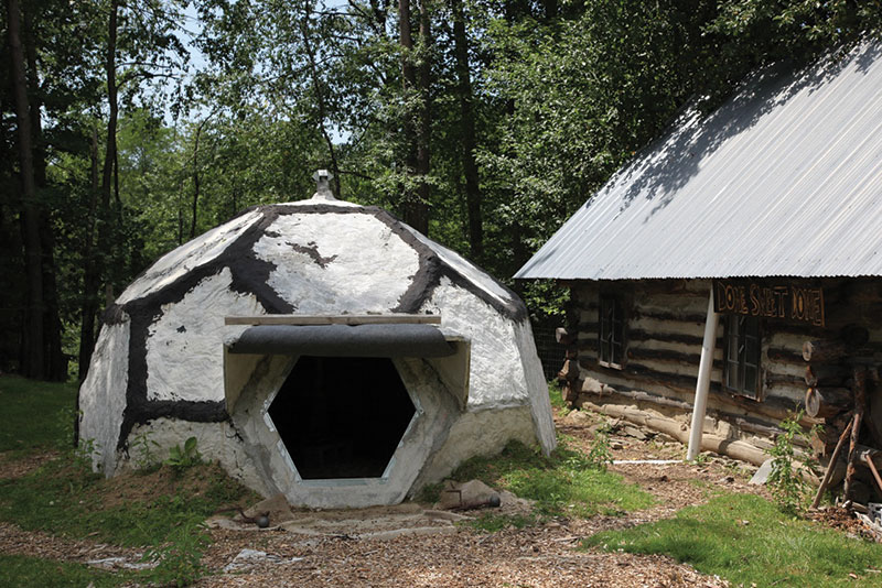
Figure 1. Completed structure. Courtesy of Meghan Holland.
Construction Methods
The Dome’s design objectives include simple construction, minimal material use, and utilizing locally available materials and labor. Construction does not require sophisticated calculations, measuring devices, or tools. The goal was to achieve a fabrication tolerance of +/- 0.25 inches during the design process; however, during assembly, misalignments of up to three inches occurred while maintaining structural integrity. The Dome’s span is fourteen feet and reaches seven and a half feet in height (Figures 1 and 2). 2- by 4-inch wire mesh fence, laid eight inches within the panel joints, connects the individual panels together.
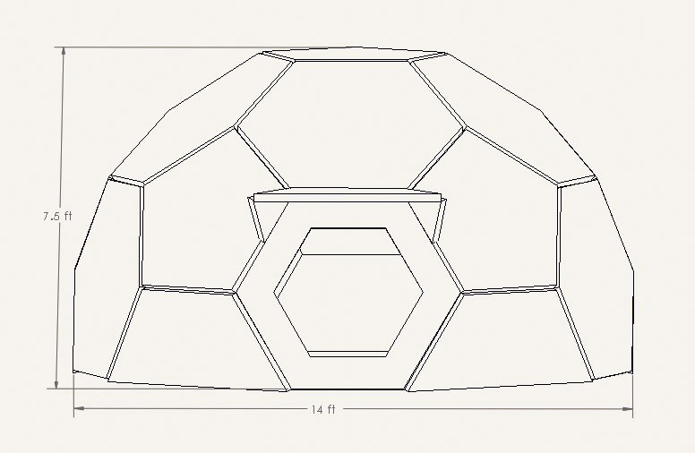
Figure 2. Diagram of dimensions. Solidworks drawing courtesy of Victoria Rude.
The Dome was designed by Thomas Tailer of Essex, Vermont using a compass to achieve the desired angles during planning and construction. The forms were placed on flat ground and lined with scrap plastic to hold the cement. The bottoms of the forms were lined with masonry cement by semi-skilled laborers, as seen in Figure 3. A carpet-cement laminate was constructed using two layers of carpet reinforcement surrounded by cement, with 14 gauge galvanized fencing wire bonded to the cement extending four inches out of individual panels to provide the panel connections (Figure 4). The carpet reduces the amount of cement necessary to make the panels, and also acts as tensile reinforcement. During loading events, the carpet will deform elastically; after the event occurs, it will have a tendency to return to its original shape. Each panel takes the shape of a pentagon or hexagon, weighing approximately 100 to 240 pounds, with a thickness of one and a half inches and with a side length of thirty inches.
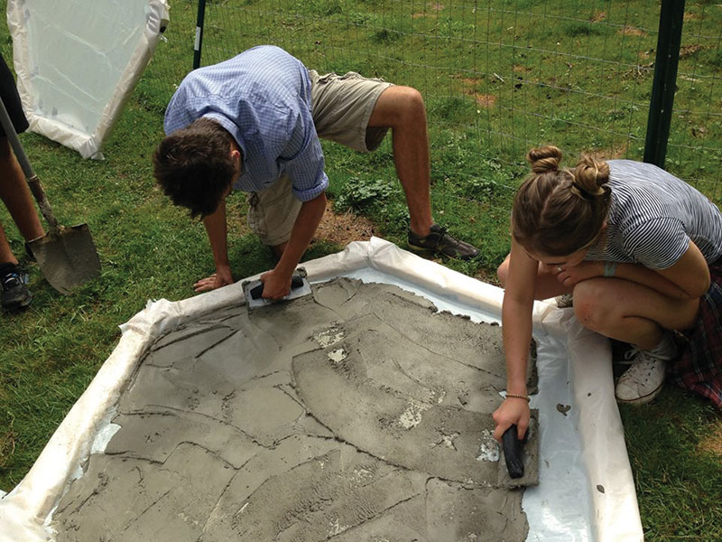
Figure 3. Panel formation of first layer. Courtesy of Hannah Marshall.
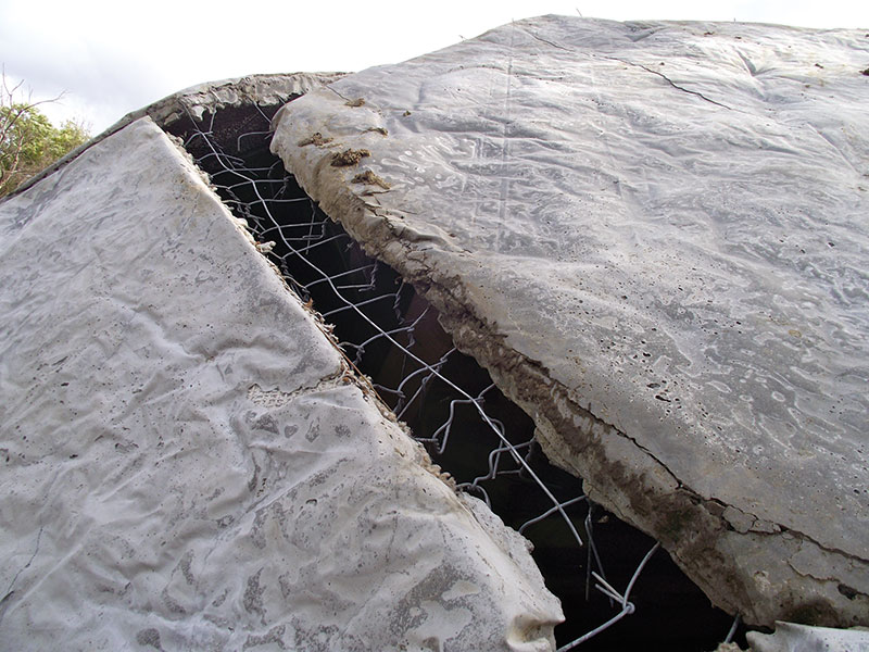
Figure 4. Attachments between the panels before addition of masonry between joints. Courtesy of Megan Strand-Jordan.
The Dome assembly uses a layering technique with three steps of construction. The first step starts at ground or base level, and connects the panel edges to each other by twisting together the protruding wires. The second step requires cantilevering panels from the ground level panels and temporarily supporting them until three sides can be wired to the structure as displayed in Figures 5 and 8. After the supported panel is wired into the structure, the temporary supports can be removed and used in attaching the next panel. The center piece is lifted into place by the use of temporary cribbing in the center of the dome. The temporary supports and cribbing are removed after all pieces are connected. Masonry cement is added between the joints, acting as a waterproofing feature and a reinforcing structural element. In addition, it prevents the wires from untwisting during large loading events. The Dome comfortably fits nine people (Figure 6), and would provide adequate shelter from extreme weather events. A chimney, stove, and external vent inserted into the structure allow for a cooking area, ventilation, and a heat source.
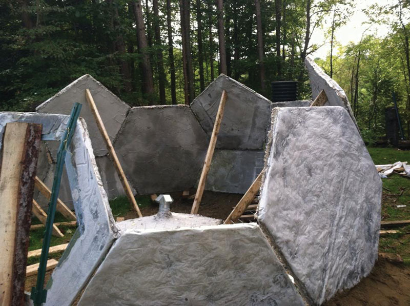
Figure 5. Temporary supported 2nd level. Courtesy of Megan Strand-Jordan.
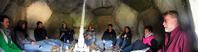
Figure 6. Nine people comfortably seated inside dome. Courtesy of Megan Strand-Jordan.
A team of students from the Governors Institute of Vermont and the University of Vermont’s Engineers Without Borders Chapter assembled the Dome. The students were unfamiliar and unskilled in construction. It took approximately 100 person hours to construct and assemble the panels and their forms. However, a semi-skilled team of laborers with greater strength, or laborers with more experience using the system, could likely fabricate a dome in 50 person hours. The material cost of the structure is approximately US $200, with the major cost being masonry cement.
Construction Challenges
Numerous challenges arose during construction of the Dome, mainly during the assembly of the panels. The first major problem emerged while trying to close the circular base of the dome. The base would not completely close due to misalignment, and the panels were extremely difficult to adjust by hand. Closure of the bottom panels was needed before the second level of panels could be placed. Construction completely stopped until the issue was resolved. A system of levers was designed to wedge the base into place and allowed the first layer to close. In order to avoid construction delays, future designs will feature the construction of a foundation before interlocking the base panels to ensure closure.
The weight of the top panel was a major issue during the assembly process. The panel’s thickness made it much heavier than other panels used. Styrofoam aggregate added to the cement mixture was not successful in substantially reducing the weight of the panel. This issue required the assembly of cribbing in the interior of the Dome to support the top panel while it was wired into the entire structure (Figure 7). The top panel rose slightly higher than the total height of the structure and was lowered onto the lightly supported second level panels by removing part of the cribbing to allow for the final wire attachments. With the roof panel in place, the structure achieved the rigidity needed to stand unsupported. To avoid this situation in future construction, designs will use smaller panels that weigh no more than 100 pounds.
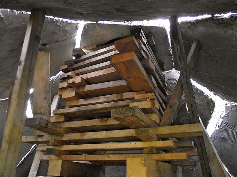
Figure 7. Inside view of interior cribbing/scaffolding. Courtesy of Megan Strand-Jordan.
Significant problems with the structural integrity of the panels arose during construction of the second level. A hexagonal panel cracked in half during transit from the mold to the structure because material shortages forced the use of subpar carpet during construction. The panel was severely damaged as an individual piece, and could not support its own weight. The integrity of the entire structure was called into question as a result of this panel failure. With winter fast approaching, entire replacement of the panel was not possible. The damaged panel was subsequently attached to the dome with the crack oriented vertically. It was believed at the time that the structure’s strength resides in its edges, and that it was unlikely that a single cracked panel would cause the failure of the entire structure. In addition, the placement and orientation of the crack took advantage of the compressive lateral forces provided by the dome shape to negate the damage done to the panel by the crack. The dome has remained standing successfully for one year with its structural integrity intact, surviving significant snow loading during the harsh 2013-14 Vermont winter and repeated freeze thaw cycles, with no apparent signs of structural damage or deterioration.
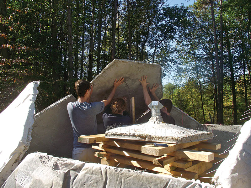
Figure 8. Second level panel supported and wired into place. Top panel with chimmney supported by cribbing in the foreground. Courtesy of Megan Strand-Jordan.
Applications/Conclusion
Conventional construction systems for housing in third world countries use reinforced masonry that is expensive both environmentally and economically, and often do not provide enough protection from earthquakes and other natural disasters. The goal of this project was to develop a new system using resources that are currently wasted or underutilized to help provide shelter to the world’s poorest people severely affected by natural disasters. The system and construction process has application to many other structures that could be built at reduced costs. For instance, this concept has the potential of creating a composting toilet from local materials for only a few hundred U.S. dollars, and the opportunity to create a useable product from waste generated within a community. A Quonset hut type structure can provide larger clear spans and more useable floor space for classrooms, workshops, or storage areas for a significantly lower cost than traditional methods, such as corrugated steel or timber structures.
This system is a green technology which supports the concept of sustainable development. The system enables slender sections resulting in less cementitious materials in the members. Approximately 5% of global CO2 emissions are contributed by the production of cement and concrete (WBCSD 2008). According to many scientists worldwide, global warming is the most destructive problem humans now encounter. This system will result in benefits from cost savings, lower embodied energy and reduced CO2 emissions when compared to conventional approaches. Using the structural analysis laboratory at the University of Vermont, basic structural property tests such as bending and buckling resistance were conducted on test panels. The results from these tests will be used in a computer model to be constructed this fall and spring, for earthquake resistance analysis.
What’s Next?
The most applicable places to build these structures would be in locations such as Haiti and other earthquake prone areas with easy access to cement. A pilot project is underway in which student volunteers from UVM will travel to Haiti with the Vermont Haiti Project and teach Haitian students how to build a structure using Dome materials and how to implement it in their communities. In addition, the team envisions a dome-like structure built right on the UVM campus, not only to attract the public’s attention, but also to get new UVM students involved in engineering projects. Finally, new structures using the carpet cement material are being designed, constructed, and tested for applicability in Vermont. The hope is to custom tailor designs to the regions of the world where these structures will be built.
Disclaimer: The Dome was built with other safety systems in place that were not included in the article for brevity. Anyone who wishes to replicate this work should exercise caution. The Dome is patent pending. The hope is that, with a patent, the work will be protected and licensing of pre-engineered structural designs to non-profits and non-governmental organizations for use in relevant countries will be feasible.▪