
The ‘X’ Brace vs. ‘V’ Brace Conundrum
As practitioners in structural design, we sometimes scratch our heads in bewilderment with new code provisions. Usually, with a little homework, we can understand the logic behind the changes and see how they lead to better performance of the end product. Unfortunately, beneficiaries of our efforts sometimes see that end product and jump to the “engineers gone wild” conclusion, accusing us of grossly overdesigning the structure when we have simply provided one that meets code.
A good example of this can be found in the ANSI/AISC 341-10 Seismic Provisions for Structural Steel Buildings, Sections F1.4a and F2.3. Among other criteria, they require beams intersected by braces to be designed for the expected strength of the braces in tension, counteracted by only 30% of the expected strength in compression of the adjoining braces. In other words, a beam intersected by the braces in a conventional “V” or chevron configuration must be designed for an enormous vertical seismic load at its midpoint. The result is a beam that at first glance seems too large to reflect a pragmatic design. Where past code provisions might have allowed a W24x76, it is now not uncommon to see a W33x241 or even larger.
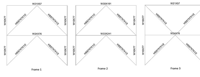
Figure 1
What is really happening in this scenario? Fundamentally, the logic does make sense. Simple nonlinear modeling serves to illustrate the concept and the benefit of this code provision. Consider Figure 1. Other than the obvious geometrical differences between Frames 1 and 3, one might conclude that they are essentially equivalent. Indeed, their weights are equal, and modal analysis calculates the exact same periods and mode shapes. These frames will thus behave the same in an earthquake, right? The answer is a qualified ‘Yes’ if no braces buckle in compression, and a definitive ‘No’ if any braces do buckle; and in contemporary seismic design, brace buckling may be characterized as a forgone conclusion. In fact, many detailing provisions in ANSI/AISC 341-10 require that frames be configured to allow and even encourage a specific mode of buckling.
What then is the primary difference between Frames 1 and 3? Frame 3 is geometrically configured with four braces, rather than two braces intersecting the beam. As such, the braces themselves provide most of the counteracting resistance required by the aforementioned sections of ANSI/AISC 341-10, and the beam size is not significantly affected. A simple pushover analysis demonstrates this concept. Frame 2, also shown in Figure 1, is geometrically equal to Frame 1, but with beam sizes increased to address the unbalanced load requirement of ANSI/AISC 341-10.
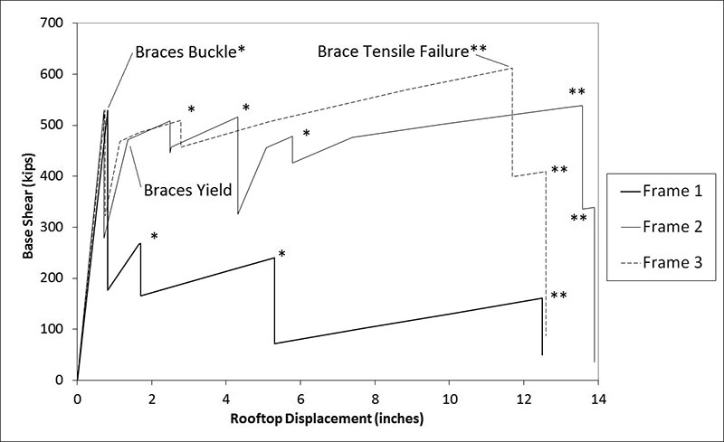
Figure 2
Figure 2 depicts pushover curves for the three frames that have been analyzed and subjected to equivalent procedures of piecewise monotonic displacement while measuring the base shear and accounting for compression buckling, tension yielding, and beam bending in the frames. For this scenario, the only difference between Frames 1 and 3 is the geometry, yet a marked difference is evident in the nonlinear performance. Both behave elastically up to about 0.75 inches of rooftop displacement, at which point the first braces buckle at the lower level. From this point forward, the behavior diverges significantly.
For Frame 1, the beam (W24x76) is subjected to an unbalanced force for which it does not have adequate strength and stiffness. As a result, the frame does not regain its strength as shown with increased displacements on the pushover diagram. Frame 3, on the other hand, has braces at the upper level configured to counteract the unbalanced forces from braces at the lower level. It has the ability to regain capacity, as measured by the base shear, roughly equal to the force at which the first brace buckled. This frame can be displaced even farther, through buckling of other braces, until reaching the point where tensile rupture of braces occurs and base shear measurements suddenly diminish.
Frame 2 of Figure 1 depicts beam sizes that might be utilized to maintain the chevron configuration, yet satisfy the seismic design provisions. These very large, very heavy beams have a flexural stiffness commensurate with the counteracting braces. As such, they can readily handle the unbalanced forces and develop a pushover curve as shown in Figure 2, capable of regaining capacity after initial buckling of braces as demonstrated by the base shear measurements.
In summary, Frame 1 is ill-equipped for significant nonlinear behavior as demonstrated in Figure 2. Frames 2 and 3 are better equipped for nonlinear behavior, but the weight of Frame 2 is nearly double that of Frame 3, and Frame 2 must accommodate very deep beams with flanges in excess of 15 inches wide. Clearly, the ‘X’ configuration is the best approach using conventional framing members. Alternative approaches for potentially mitigating these pitfalls include “zipper columns,” which distribute the unbalanced forces across multiple levels of beams and bracing, and advanced technologies such as buckling restrained braces.▪
A similar article was published in the Structural Engineers Association-Utah (SEAU) Monthly Newsletter (November, 2011). Content is reprinted with permission.