
NYNJ Rail is the last remaining car float operation in the metropolitan New York area. This shortline railroad operates between Jersey City, NJ and Brooklyn, NY moving freight across New York Harbor, and is one of four remaining car float operations in the United States. The transfer bridge concept originated in the mid 1800s with a ferry between Havre de Grace and Perryville, MD for the Camden & Amboy Railroad and the Philadelphia, Wilmington and Baltimore Railroad. Rail cars were transported across the river by moving them from land to a barge by means of a transfer bridge. The rail cars are then unloaded at a similar facility across the waterway. In the late 1800s, New York City was a major manufacturing and industrial center requiring massive transfer of raw materials and finished goods. The base of the industry was on Manhattan Island, requiring materials to be moved by water between New York and New Jersey, or through the only land route across the Spuyten Duyvil (northern tip of NYC), which was controlled by Cornelius Vanderbilt’s New York Central Railroad. All other railroads terminated along the New Jersey side of the Hudson River, and goods were moved either by lighter (small barge) or car float. At the pinnacle of this period, over 6000 freight cars per day were transported across the river by car float.
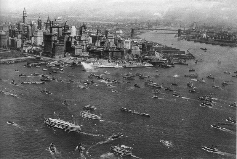
Figure 1. NY Harbor Circa 1928.
Super Storm Sandy caused severe damage to both the Jersey City and Brooklyn transfer bridge facilities. A temporary pontoon structure was constructed in Jersey City while a new permanent bridge is designed.
Transfer Bridges
The structure that allowed rail cars to be loaded onto car floats is the float or transfer bridge. The transfer bridge is unique in that it must function as a movable bridge for the purpose of allowing adjustment between the top of rail elevation on land and on the car float. In New York Harbor, the typical tidal fluctuation is up to10 feet. As this relative elevation change is due to tide and car float freeboard changes, the bridge must adjust to provide the connection between car float and land. This elevation adjustment typically occurs over the 30 minute load/unload cycle. While both rail and highway movable bridges are opened to allow marine traffic to pass, they do not operate under live loads as do transfer bridges. Transfer bridge live loads include locomotives and rail cars that vary in weight due to their changing cargo. Today rail car loads can be in excess of 286 kips. In addition to operating under live load, these bridges provide a mooring connection to the car float. This mooring connection can impose significant loads onto the bridge structure, even though fender systems and mooring dolphins may be used. These loads include the propulsion from the tug boat as well as wind loads, causing a moment at the end of the bridge.
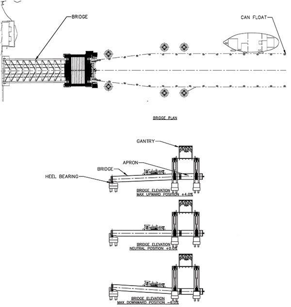
Figure 2. Transfer bridge arrangement.
In Figure 2, a typical arrangement between the car float and the transfer bridge, along with the capacity for elevation adjustments, is shown for a mechanically driven structure. This structure uses hydraulic cylinders suspended from a gantry to raise and lower both the bridge and the apron. In older designs, the bridge and apron utilized counterweights to balance the dead load of the structure. The reality of these structures is that the dead load represents approximately 20% of the total load on the structure. For this new transfer bridge, the cost of the counterweight system was not justified compared to increasing the hydraulic cylinder size.
Another design utilizes a pontoon (floating structure) to support the bridge. This system relies on the pontoon to adjust the bridge elevation based upon tidal variation, but does not compensate for the car float freeboard (loaded/unloaded). The size of the pontoon is based upon the dead load of the bridge and the expected change in freeboard of the car float. A simple calculation is used to determine the volume of water that must be displaced to compensate for the changes in car float loads. The volume of the pontoon is then sized appropriately. The railroad operator must adjust the elevation between the car float and bridge by loading the bridge (usually with a locomotive) such that the toggle bars can be engaged. This approach requires substantial operator skill and can limit the speed of loading and unloading operations.
Based upon the range of tidal variation, the length of the bridge and apron are adjusted such that the maximum angular change between the land, bridge, apron and car float do not exceed the allowable for the rail cars (prevent bottoming). Most freight cars do not pose a limitation compared with hopper cars which dump the cargo through the bottom. The length of the bridge and apron determines the maximum positive and negative angles that will occur over the operating range of the bridge and car float. Transfer bridges generally range from 80 to 150 feet in length. In order to compensate for the angular changes of the rail during tidal extremes, the bridge shown is articulated. The articulated design allows the apron to make a hard connection with the car float utilizing a toggle bar arrangement (Figure 3). The toggle bars are critical to maintain top of rail alignment between the bridge and car float. These toggle bars resist large loads, as the car float tends to rotate as the freight cars are moved on and off. It is common for the operators to develop a loading/unloading sequence that accounts for the shifting load conditions.
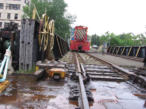
Figure 3. Toggle bars connecting the car float to the transfer bridge.
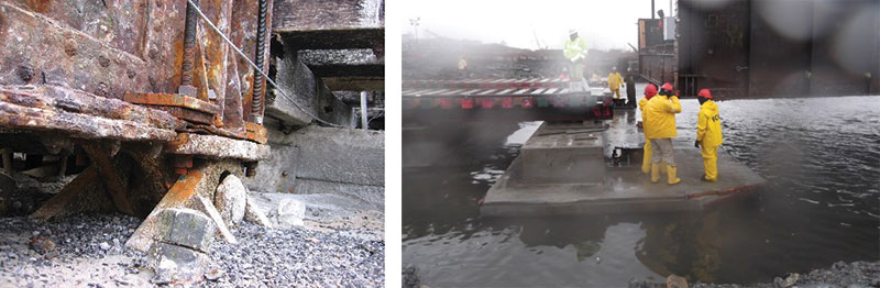
Figure 4. Hinge pin arrangement connecting the transfer bridge to the abutment.
A key feature of these bridges is that components of all loads are transmitted to the substructure through the hinge pin arrangement (Figure 4). The hinge pin is a critical element of the entire system. These loads include: live load, dead load, traction/braking loads, mooring loads (tug boat loads and moments from wind load on the car float), as well as seismic loads. Due to the operation of these structures, the seismic loads tend to govern. It is not uncommon for hinge pins to see loads ranging from 300 to 700 kips in the longitudinal direction, 180 to 800 kips in the vertical direction, and up to 230 kips transversely. The original design was a simple pin and clevis arrangement. For the loads of today’s freight cars, the hinge pin assembly becomes extremely large. In order to resolve the loads in compliance with AREMA design standards, a different approach was taken. A saddle design (heel bearing) was developed, both simplifying the construction and improving the reliability of the hinge over time (Figure 5). The transverse loads are resolved using a mechanical device which is a movable key located in the center of the pier. An added design challenge includes regular submergence of the hinge pin arrangement. The selection of materials for this component is critical to provide the capacity, but also to provide reliable operation over an extended period (30 years).
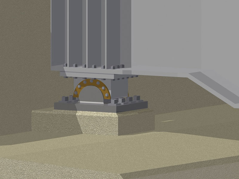
Figure 5. Heel bearing.
These “workhorse” bridges truly provide a unique challenge for engineers to showcase their skills.▪