
Recent advances in concrete reinforcement technology have led to the availability of high strength (as high as 100 ksi) and large diameter (as large as 3.5 inch diameter) reinforcing bars for concrete structures. These bars are available with thread-like deformation patterns that permit the use of complimentary connection and anchoring hardware, and facilitate prefabrication of large reinforcing cages. These advances in material and manufacturing technologies can be combined to create High Performance Concrete Reinforcing (HPCR) systems that can be used to significantly reduce the quantity of reinforcing and associated material and labor costs, and create potential schedule savings for concrete building structures.
However, the implementation of these new reinforcing materials into the design of concrete structures can pose some significant challenges, as current design practices and prescriptive code procedures do not always address some of the unique performance characteristics of these materials. In an attempt to address some of these challenges, design recommendations for using high strength reinforcement have been presented in a few publications, most notably ACI Committee Report ACI-IGT-6R-10 and the National Cooperative Highway Research Program Report-679.
As the availability of these materials becomes more prevalent, it is important that engineers understand the primary challenges and limitations associated with utilizing HPCR systems. Engineers should become familiar with effective optimization techniques using these advanced reinforcing systems in order to exploit their full benefits, which can result in more efficient and sustainable/cost effective structural designs.
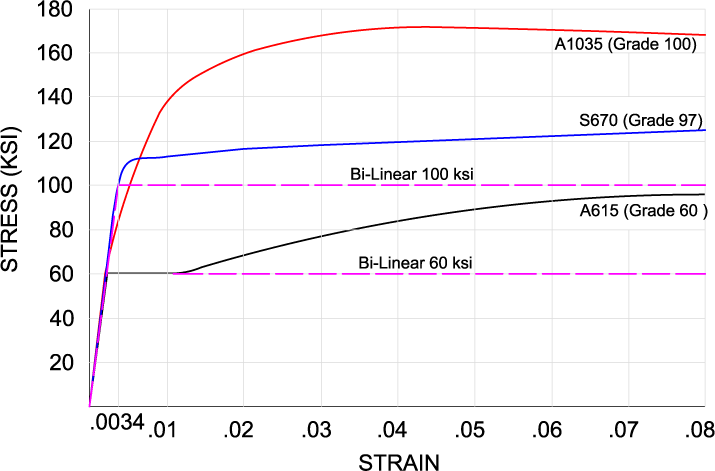
Figure 1. Comparison of two commercially available high strength reinforcing materials and conventional ASTM A615.
“Trouble with the Curve”
High strength reinforcing materials are generally considered those with a yield stress in excess of 80 ksi. Such materials have been in existence for quite some time and are used regularly in Japan and Europe. Figure 1 shows the stress strain curves for two such high strength reinforcing materials that are commercially available in the U.S., along with that of conventional A615 Grade 60 reinforcing. One of the common characteristics of most high strength reinforcing materials is their lack of a well-defined yield point, exhibiting more of a roundhouse transition above the proportional limit. However, it is also readily apparent that although the two higher strength materials utilize a similar design yield stress of approximately 100 ksi, the stress strain curves are quite different. The Grade 97 material, while more similar in performance to conventional A615 and perhaps even closer to A706, within the low to moderate strain range, does not exhibit nearly the same degree of strain hardening in the higher strain ranges. Alternatively, the Grade 100 material exhibits a rapid and significant strength gain even at very small strains, but then little to no strain hardening beyond approximately 0.04 strain.
The ACI 318 prescriptive design provisions are based on an idealized bi-linear elastic-perfectly plastic stress strain relationship. This is a reasonable assumption for conventional A615 and A706 materials because they do not deviate significantly from the bi-linear idealization until the higher strains that would be associated more with high seismic applications. For those conditions, ACI limits the allowable deviation from the bi-linear relationship, in addition to accounting for the actual material strength rather than an assumed strength (the “overstrength” concept). However, when the actual stress-strain behavior deviates significantly from the idealized bi-linear relationship at low to moderate strain levels, special consideration is necessary to ensure ductile behavior under normal loading condition, in order to account for the “overstrength at low strain” issues associated with some of these materials. For these reasons, it is often more prudent to consider the full non-linear stress strain relationship of high strength reinforcing materials for design, rather than a simplified bi-linear relationship. In some cases, the ACI-318 prescriptive procedures are simply not applicable to high-strength reinforcing material and require performance-based design methods.
Threaded Bar Reinforcement Systems
Threaded bar reinforcement has been used for many years in foundation and post-tensioning applications, and occasionally as reinforcement for building structures. A number of large-scale building projects in New York and New Jersey recently utilized the HPCR systems as the primary longitudinal reinforcement in columns and shear walls.
Threaded reinforcing bars are characterized by their continuous thread-like deformations, which provide equal or better bond than conventional rebar deformations. The thread-like deformation also provides a threading mechanism to facilitate the use of complimentary threaded accessories, such as couplings and anchors, at any location along their length (Figure 2). Threaded reinforcing bars can be cut anywhere along their length with no additional machining required. These features allow for full tension couplers to be used economically and efficiently because a full tension threaded bar coupler is often less expensive than the material cost of the required lap splice length. Additionally, using couplers on the full range of available threaded bar sizes eliminates the need to try to limit bar sizes to #11, which is the current limit beyond which conventional couplers are required. Similarly, anchorage hardware is easily installed onto the ends of threaded bars, eliminating the need for hooks, or machine threaded, or welded, headed anchors.
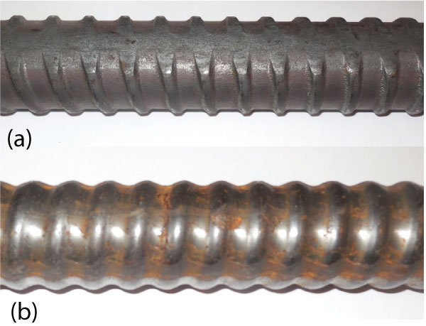
Figure 2. Typical features of threaded reinforcing bars. Continuous thread-like deformations are either (a) hot rolled or (b) cold rolled or cut into bar.
Benefits of HPCR
Combining the large size, high strength and thread-like deformations of HPCR systems significantly reduces concrete reinforcing quantities. The first source of quantity reduction is due to the higher strength of the HPCR materials. The second source is the elimination of required lap splice lengths. As a simple example, one #24 (100ksi) threaded reinforcing bar can replace seven #11 (60ksi) conventional rebar, yielding a 37% decrease in material weight. Further reductions are realized with the elimination of lap splice lengths for the seven #11 bars, which may be as much as 65%. Even after accounting for the cost of the full tension coupler for one #24 – 100ksi threaded reinforcing bar, the material cost savings is significant. Other constructability and logistical benefits include less congestion, less pieces to fabricate transport and install, less labor and less tie reinforcing, when present. The drawback of a #24 bar being too heavy for hand-installation is readily offset by the advantage of threaded features of the bars, grouping multiple bars into cages, or modules for off-site pre-fabrication. The cages can then be delivered when needed and erected relatively easily with the use of a crane (Figure 4).
Figure 3 illustrates a realistic example of how the features of HPCR systems replace, and oftentimes increase, the capacity of shear walls in tall building structures. HPCR systems can consolidate the capacity of large quantities of conventional reinforcing into a few optimally placed clusters of HPCR. The reinforcement between these clusters can be significantly minimized to ideally be only the required minimum reinforcement. Additionally, the clusters can be fabricated into two-story high cages, saving erection costs on alternate floors. Alternately, staggering the two-story cages would require only half of the cages to be installed on any one floor.
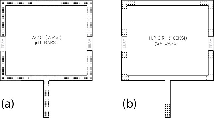
Figure 3. Comparison of alternate design of high rise core walls reinforced with (a) conventional #11 Grade 75 bars and (b) #24 Grade 100 threaded bars.
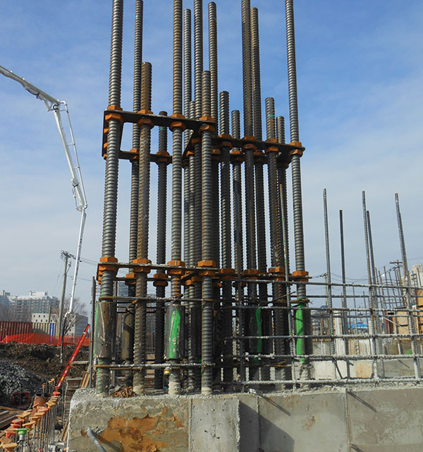
Figure 4. Example of a prefabricated shear wall cage of HPCR.
Code Considerations
ACI 318-11 does not explicitly address the use of high strength reinforcing materials. Section 3.5.3.2 currently limits the yield stress to the stress corresponding to a strain of 0.35%. This limitation is partly to ensure that the assumption of an elasto-plastic stress strain relationship for materials that lack a well-defined yield point will not lead to unconservative calculations of member strength. The limitation is also intended to provide some measure of control for service level cracking.
Section 9.4 further limits the value of the design yield stress to 80 ksi, to be compatible with the maximum usable compressive strain limit of 0.003 (Section 10.2.3). The maximum compressive strain of 0.003 assumes rapid loading conditions without considering actual loading sequence or long-term effects. The use of a higher compression yield stress can be justified by considering the long term redistribution of creep and shrinkage strains from the concrete to the reinforcement. Although ACI 318-11 does not address this phenomenon, Section 9.5.2.5 acknowledges it indirectly by allowing for a reduction in the long term component of deflections based upon the redistribution of creep and shrinkage strains to compression reinforcement. For vertical elements subjected to load reversals, such as shear walls, consideration of such strain/stress redistribution must account for any strain recovery that occurs during unloading and tension loading phases.
ACI 318-11 enforces minimum ductility requirements for flexural members in Sections 10.3 and 9.3 by ensuring that there is sufficient straining of the steel between service loading and nominal strength. However, the tension and compression control limits specified in these sections were developed for conventional A615 reinforcing material, and thus must be modified for high strength reinforcing materials to achieve similar ductility levels.
Strength Design Considerations
Regardless of the level of sophistication used for the design of concrete members with HPCR, any design must still respect the basic tenants of the ACI 318 design philosophy. Foremost among them is the assurance of ductile failure modes for flexural and tension members. Equally important is the assurance that such ductile failure modes are not prevented or otherwise limited by a less ductile supporting mechanism. For example, if the “actual” capacity of a reinforcing material at a specified strain level is 50% greater than the assumed value, then the development, splicing, anchorage, etc. of the reinforcement at that strain level must be capable of developing or supporting similar actual strengths. This is of critical importance in reinforced concrete design because the limit states design philosophy of ACI 318 is strain-based, not stress based.
The strength design methods used for HPCR can typically employ the same code-based procedures and formulae used for conventional reinforcing, as modified in the design guides and recommendations of ACI (ACI-IGT-6R-10) and the National Cooperative Highway Research Program (Report-679). Engineers must exercise greater care in determining the appropriateness of any such design procedures and formulae due to some of the unique challenges and limitations of HPCR systems, as previously described; however, the engineer has the option of using non-prescriptive performance-based design procedures.
Figure 6 illustrates a standard P-M interaction diagram for the shear walls shown in Figure 3. The diagrams use nominal strength because the transition zone for the applicable phi-factors between tension-controlled and compression-controlled limits is different in conventional reinforcing materials and high strength materials. The HPCR design (Figure 3a) requires 30% less reinforcement area than the wall reinforced with conventional Grade 75 bars (Figure 3b). Redistributing the HPCR to their most effective locations achieves an equal or greater wall stiffness with an overall lesser reinforcement quantity, while also increasing the moment capacity for the same axial capacity (Figure 6).
The use of HPCR in the superstructure may also result in special design considerations for the foundation elements. The effective use of HPCR in shear walls can result in large localized concentrations of high strength reinforcement at wall ends (Figure 3). This may impose higher than usual foundation anchorage and pull-out, or shear, demands on foundation mats and footings. The use of shear reinforcement or distribution elements (subgrade walls, grade beams, etc.) can be used to distribute the force concentrations over a longer length of the foundation.
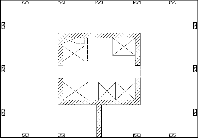
Figure 5. Representative floor plan and coupled shear wall arrangement for a high rise building.
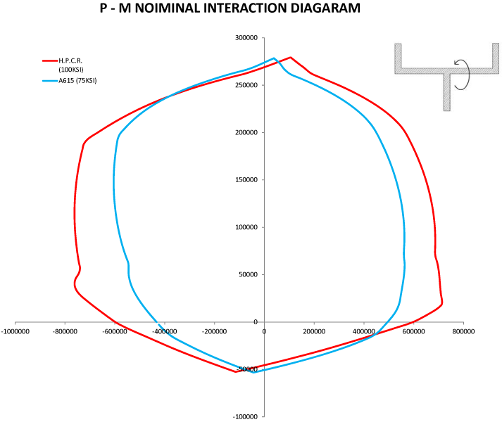
Figure 6. Comparison of the P-M nominal interaction diagrams for the lower shear wall in Figure 5 with the reinforcement distributions shown in Figure 3.
Stiffness Design Considerations
High strength reinforcing materials generally exhibit larger tensile strains at service level loading than conventional reinforcing materials, which will result in larger deflections and wider crack widths. Because one of the primary benefits of utilizing HPCR is to decrease the total reinforcement quantity, the effects of any such reductions in reinforcement quantity on the stiffness of the structural elements may become an important consideration. The relevancy depends on to what degree, if any, the engineer considers the reinforcement in his or her stiffness calculations. Many engineers still utilize effective stiffness modifiers (i.e. Ieff = 0.5Ig, etc), so it may not be necessary to use a more detailed approach for HPCR. However, in cases where the structural elements are stiffness-controlled, or where HPCR is being proposed as a value engineering alternate, it may become necessary to verify that stiffness of the elements reinforced with HPCR is not less than that of conventional reinforcement.
Non-linear moment-curvature analysis is an effective way to compare the stiffness of sections reinforced with conventional versus high strength reinforcing and incorporates the actual stress-strain behavior of the materials, as well as the spatial distribution of the reinforcement. If there is significant axial force due to gravity or lateral loading, such as the case with coupled or linked shear walls in figure 5, then the moment curvature analysis can incorporate those axial forces in the analysis. Since curvature (Ø) = M/EI, the secant slope of the moment-curvature diagram up to the service moment, can be used as the effective stiffness EIeff. As Figure 7 shows, the stiffness of the shear wall with HPCR is greater than that of the conventional reinforcement, even with 30% less reinforcement, because of the more efficient location of the reinforcement toward the extreme fibers.
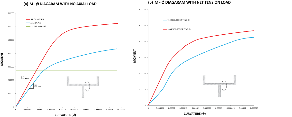
Figure 7. Comparison of the moment-curvature diagrams for the walls in Figure 3 with (a) no net tension load and (b) high net tension load.
Summary
Features of HPCR systems help significantly reduce the total reinforcement quantities for concrete structures because of their high strength, large size and the ability to couple and anchor the bars efficiently and economically. Additionally, their use permits higher concentrations of HPCR to be placed at optimal locations to further increase their effectiveness. As is often the case, proposing HPCR systems as a value-engineering alternate only provides a simplified direct substitution which often fails to exploit the full advantages of HPCR systems. A direct substitution almost invariably results in a decrease in section stiffness because the area of reinforcing is being decreased, without any compensation that may be achieved by concentrating the reinforcing at a more efficient location. However, when integrating HPCR into the original design, the engineer can incorporate the HPCR features and maximize the advantages using appropriate design procedures and recommendations for strength and stiffness.▪