
High-strength welded wire reinforcement (WWR) mats offer a viable alternative to traditional tied rebar mats in tilt-up concrete panels. Using WWR can result in an overall decrease in reinforcing steel tonnage for the project, and allows much faster placement. Both of these factors can improve the project schedule and budget. However, there are critical differences in the panel design that must be considered.
WWR is manufactured using stock coils of cold-drawn steel wire, either smooth or deformed, which is then fabricated into sheets capable of being shipped. Individual transverse wires are dropped in place along the length of the continuous longitudinal wires and welded at each crossing. The process is highly automated, resulting in accurate and predictable spacing of wires, which can be customized as needed for individual project requirements. After fabrication, sheets can be bent into nearly any shape, including tied column cages. These are frequently required in tilt-up construction for narrow strips adjacent to openings where placement of traditional rebar is especially difficult and time-consuming.
WWR is available in several grades of steel, as covered under ATSM A1064 (smooth fY, MIN = 65 ksi, deformed fY, MIN = 70 ksi). Deformed wire with fY = 80 ksi is commonly specified and readily available. In some cases, the use of higher-strength reinforcement can reduce the overall area of steel required, resulting in greater efficiency and decreased quantities.
There are two primary issues with high-strength WWR substitution that impact the panel design. First, with higher reinforcing steel strength comes proportionally higher strain in the concrete. For heavily reinforced panels, this can result in a section that is not tension-controlled, violating one of the primary criteria of tilt-up panel design under ACI slender wall provisions. It is therefore critical to reduce the area of steel to maintain the same strain relationship within the design section. Using this reduction is common when a contractor or rebar supplier proposes WWR substitution for rebar, but should always be verified by the engineer prior to approval. Some suppliers may propose a direct one-for-one substitution based on area of steel only. At first glance, this may appear to include “bonus strength,” but it is not appropriate for slender wall design.
The second issue pertains to second-order (P-Δ) effects, which have a significant impact on slender wall design. Using a proportional ASfY (rebar) = ASfY (WWR) substitution may resolve issue #1 above, but the lower steel area also reduces the cracked-section moment of inertia for the concrete panel (ACI 318-11, Eq. 14-7). In turn, the deflection (ΔU) due to second-order moments increases, reducing the overall flexural capacity of the panel (Eq. 14-4, 14-5). In such cases, either greater steel area or increased concrete strength is necessary. This effect is especially apparent in panels with a single mat of reinforcement centered in the panel depth. Panels with two reinforcing mats have a greater effective section depth, which typically limits P-Δ effects to a manageable level where a steel area reduction is achievable.
When designing with WWR, it is possible to provide a more accurate quantity of reinforcement than with traditional rebar. In an effort to keep the bar size and spacing simple and practical, greater amounts of steel are frequently provided than truly necessary for the design (e.g., using #5 @ 6 inches instead of #5 @ 7.5 inches). With the greater variety of wire diameters that are readily available, and more accurate spacing control with shop-fabricated WWR sheets, it is possible to design panel reinforcement much closer to the true area of steel necessary (D9 @ 4.5 inches is just as easy as D20 [#4 bar] @ 6 inches). On a large project, this savings in steel tonnage can be significant.
For double-mat panels with reinforcement at each face, horizontal bars are often kept at a tighter spacing than what would otherwise be required by code to control shrinkage cracking (18 inches maximum per ACI 318; 15 inches maximum per National Building Code of Canada). Bar sizes are driven somewhat by handling concerns; often #3 bars are avoided. This can result in horizontal steel significantly greater than the minimum specified by ACI. Using WWR, wires with a smaller diameter and closer spacing can provide more uniform crack control using less steel area. Wire sizes need not be limited due to handling concerns since each intersection is welded, providing inherent stability during transportation and construction.
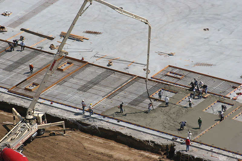
These panels were reinforced using a single uniform mat of WWR throughout, with tied rebar cages (two mats of rebar) added at jamb strips. Courtesy of Lithko Contracting, Inc.
One particularly interesting application of WWR for tilt-up construction is at narrow panel strips adjacent to doors. Manufacturing and warehouse facilities frequently have relatively tall load-bearing panels with narrow jamb strips at dock doors, as illustrated in the Figure. These jamb strips frequently require tied column cages, which are cumbersome and time-consuming to fabricate from rebar in the field. In most cases, a WWR cage can achieve the same design intent while incorporating both the vertical reinforcing and ties into a single shop-fabricated assembly. Jamb cages can be dropped straight from the truck into the form, rather than spending valuable hours field-tying them. Through the use of smaller-diameter wire “ties,” bend radii can be minimized (wire = 2*db vs. rebar = 4-6*db), permitting a double mat of reinforcing in a panel thickness that otherwise could be too congested. Using smaller wires can also provide better confinement, with less risk of segregation during concrete placement.
For illustration purposes, consider the following tilt-up panel designs, using ACI 318-11 section 14.8 slender wall provisions. For simplicity, a single load combination (D+W) is considered.
PANEL #1: (Single Mat)
Panel Criteria:
Panel span = 31 feet, 0 inches
Thickness = 7¼ inches, single mat centered
DL = 500 plf, WL = 20 psf
ΔMAX = h/150 = 2.48 inches
Material Properties:
f’C = 4,000 psi
fY = 60 ksi (mild steel rebar)
fY = 80 ksi (WWR)
Rebar Option:
AS,VERT = 0.44 in2/ft (use #6 @ 12 inches)
AS,HORIZ = 0.174 in2/ft (use #4 @ 12 inches)
Steel strain = 0.0101
MU = 82.6 kip-in/ft
ϕMN = 83.3 kip-in/ft
Actual steel weight = 2.17 psf
WWR Option:
AS,VERT = 0.39 in2/ft (use D20 @ 6 inches)
AS,HORIZ = 0.174 in2/ft (use D9 @ 6 inches)
Steel strain = 0.0083
MU = 95.1 kip-in/ft
ϕMN = 95.4 kip-in/ft
Actual steel weight = 1.97 psf
Designing the section using 80 ksi WWR, the required reinforcement reduces slightly. Note that a direct ASfY substitution for WWR would provide 0.33 in2/ft and an equivalent ϕMn = 83.3 kip-in/ft, but the required moment capacity increases due to the reduced cracked-section moment of inertia. Overall panel steel area decreases slightly due to the additional wire size and spacing options.
PANEL #2: (Double Mat)
Panel Criteria:
Same as Panel #1, except reinforced at each face
Rebar Option:
AS,VERT = 0.205 in2/ft EF (use #4 @ 12 inches EF)
AS,HORIZ = 0.174 in2/ft (use #4 @ 18 inches EF)
Steel strain = 0.0337
MU = 62.4 kip-in/ft
ϕMN = 62.4 kip-in/ft
Actual steel weight = 2.23 psf
WWR Option:
AS,VERT = 0.17 in2/ft EF (use D12 @ 8 inches EF)
AS,HORIZ = 0.174 in2/ft (use D6 @ 8 inches EF)
Steel strain = 0.0314
MU = 67.5 kip-in/ft
ϕMN = 68.1 kip-in/ft
Actual steel weight = 1.84 psf
For the double mat panel, the reduction in actual steel area using WWR is significant (17.5% less). Because the horizontal wires for WWR can be smaller in diameter and more closely spaced, the same (or better) crack control can be accomplished using less steel. A portion of these savings (10%) occurs simply due to the increase from 60 to 80 ksi steel.
PANEL #3: (Typical Dock Door Jamb Strip, Double Mat)
Panel Criteria:
Same as Panel #2, but jamb strip width = 2 feet, 3-inches
Rebar Option:
AS,VERT = 0.58 in2/ft EF (use #6 @ 9 inches EF)
AS,HORIZ = 0.174 in2/ft (use #3 closed ties @ 6 inches)
Actual steel weight = 5.50 psf
WWR Option:
AS,VERT = 0.48 in2/ft EF (use D16 @ 4 inches EF)
AS,HORIZ = 0.174 in2/ft (use D5 @ 6 inches EF)
Actual steel weight = 3.94 psf
For jamb strips, the WWR sheet can be bent into a closed cage, including both the vertical reinforcing and horizontal ties.
Conclusion
When properly designed, the use of WWR can improve the economy and performance of a tilt-up project. For engineers, specifying WWR can result in a more accurate reinforcement design with better confinement and control of shrinkage cracking. For contractors, the use of WWR can simplify installation and result in significant labor and schedule savings. Material savings for single mat panels are typically minor, but are more significant for double mat panels. Involvement of the tilt-up engineer is always critical to ensure that the WWR utilized is appropriate for slender wall design.▪
For more information on WWR applications, visit the Wire Reinforcement Institute website. A number of publications, design guides, and design tools are available.