
A completed tilt-up structure relies upon connections to the roof and floor diaphragms to transfer lateral loads to a lateral force-resisting system, such as shear walls or bracing. During construction, however, temporary wall bracing is needed to resist lateral forces. The most significant lateral force that most panels will experience is wind loading.
Having adequate temporary bracing of tilt-up panels is imperative for jobsite safety. The Occupational Safety and Health Administration (OSHA) requires that tilt-up concrete panels be temporarily braced to prevent panels from overturning or collapsing during the construction of a tilt-up structure (Title 29, Code of Federal Regulations, Standard 1926.704). However, OSHA does not specify how to prevent tilt-up wall panels from overturning or collapsing.
Bracing must be carefully engineered to resist all reasonably expected wind loads, just as panels are engineered to resist in-service loads and lifting stresses; the placement of braces and the materials used to resist the brace forces cannot be improvised. To assist in the structural design of temporary bracing, the Tilt-Up Concrete Association (TCA) provides a guide known as the TCA Guideline for Temporary Wind Bracing of Tilt-Up Concrete Panels during Construction. The guideline defines parameters by which the bracing scheme should be designed.
There are a number of ways to provide resistance to the forces transmitted through tilt-up braces during the construction period, such as poured concrete “deadmen” (or footings), helical ground anchors (HGAs) or using a permanent slab-on grade.
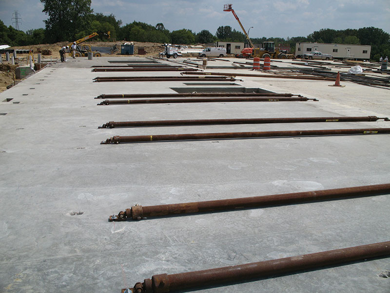
Wall panel temporary braces attached to the inside face of wall prior to panel erection.
HGAs are manufactured steel foundation elements that consist of a solid steel square bar shaft with one or more steel helical plates welded onto the shaft at predetermined spacing. They are placed directly into the foundation soil and are connected to the typical wall panel pipe braces using an alternate connector. They are installed in the ground at the same angle as the wall braces that attach to them. HGA design is typically done by the anchor manufacturer, who reviews the soil conditions at each project site and then bases the required soil embedment length for their anchors upon these soil conditions. HGAs essentially work as screws and must be installed to a certain torque to attain the loads from the steel braces and transfer them into the ground for both tension (pullout) and compression (bearing) resistance to wind loads.
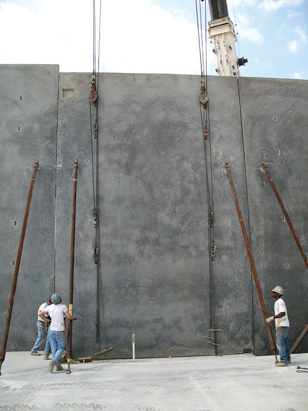
The panel erection crew winding the temporary braces for final plumbing of the wall panel during erection.
Utilizing a slab-on-grade for bracing is common and typically is the most efficient and cost-effective form of bracing. However, until recently, neither OSHA nor the TCA guideline assigned responsibility for designing the slab-on-grade for construction loads due to tilt-up wall bracing. Most of the time, the slab-on-grade is only designed for service loads, without consideration of construction loads due to panel braces. Because of the sequencing of wall panel shop drawing generation and lifting and bracing design (which is often done by a wall panel specialty engineer hired by the tilt-up contractor), it is also common for the brace loads to be determined after construction has already begun, when it is too late to design the floor slabs appropriately. For this reason, in early 2014, the TCA released a supplementary statement intended to assign responsibility for the structural design for bracing and ensure that this design happened closer to the beginning of a project, as follows:
The Owner’s designated representative for construction shall be responsible for assigning a qualified firm to review the floor slab capacity for the bracing of the tilt-up panels in accordance to the latest edition of the TCA bracing guidelines.
In addition to increasing jobsite safety, a well-sequenced and well-executed erection process improves the cost-effectiveness of tilt-up construction. Temporary wind-braces are an integral part of this erection process.
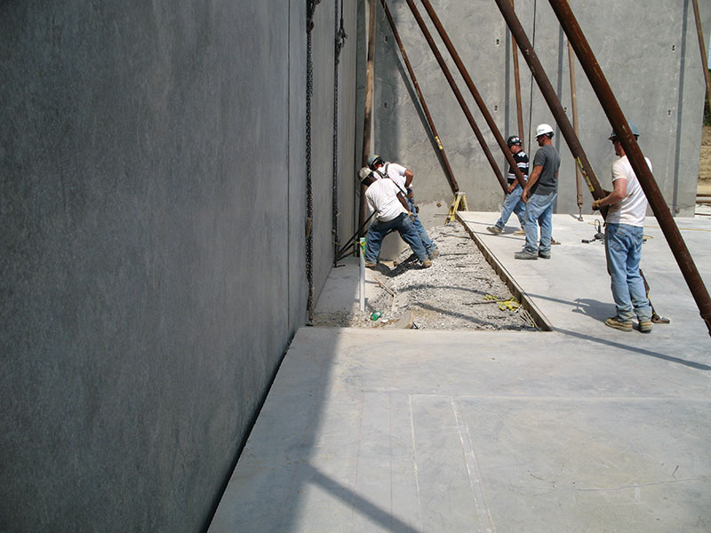
The panel erection crew using pry bars to position the panel into the proper location on the footing.
What Constitutes a Wind Load?
The recommendations established by the TCA do not address loss of property, but are set according to the limits of life safety considerations. The guideline is based on Risk Category I structures, defined as “Buildings and other structures that represent a low risk to human life in the event of failure.” This category was selected because the guideline is strictly limited to structures that are under construction. The guideline also does not address high wind events, such as tornadoes and hurricanes. It is expected that a construction field office would have the site cleared of personnel when excessive wind speed is imminent.
Specific recommendations contained within the guideline have evolved over time, alongside the evolution of tilt-up design itself. As panels have gotten taller and panel shapes more sophisticated, the guide moved away from a blanket recommendation that was intended only for small, uniform panels and toward an analytical process based upon ASCE/SEI Standard 37- 02, Design Loads On Structures During Construction. The current version of the guideline tabulates wind forces for tilt-up panels as tall as 100 feet.
While 37-02 forms the basis for design recommendations, the TCA guideline now uses wind speed set forth by updates in the ASCE 7-10 provisions. These provisions identify a design wind speed of 105 mph for Class I structures in most areas of the United States, based upon historical wind speed data. However, the guideline recommends that the 105 mph wind speed be multiplied by a factor of 0.80 (which is permitted by the ASCE for projects whose duration is six weeks to one year), resulting in a wind speed of 84 mph for calculating brace loads. Areas of the country that are frequently exposed to wind speeds above 105 mph are identified in the ASCE’s Basic Wind Speed map as “Special Wind Regions.” These zones require a higher construction period design wind speed than normal.
The panel erection crew using an extendable level to check plumb of the wall panel.
Bracing Basics
Brace manufacturers typically publish design manuals, making it easy to select the proper brace size and capacity for a broad range of wall panel heights. Installation guidelines, proper orientation and limitations are also typically published by the manufacturers within the manuals. A minimum of two braces per panel should be used; however, depending on the panel geometry, more braces may be required.
Not only are braces used to resist wind loads on each panel, they are used during erection to plumb the wall panels. Tilt-up panel braces have threaded ends that allow for winding to shorten or lengthen the brace, and thus pull the top of the wall panel inward or push it outward for final plumbing.
Some braces may require a sub-support system of knee, lateral and end bracing to increase their strength against a buckling failure. However, to simplify installation, it is typically preferred to utilize larger/stronger braces or more braces at a closer spacing in lieu of using a knee bracing system. In some circumstances, the anchorage of the brace to the slab or wall panel, rather than the capacity of the brace itself, will control the maximum brace spacing.
Braces may be attached to the panels before or after erection. However, when panels are cast inside face up and the braces will be attached to a resisting system on the inside of the building (such as the slab-on-grade), the preferred method is to attach the braces to the panel before lifting to increase erection productivity. In this case, the braces are placed just under the roof diaphragm so that, when the roof installation is complete, the braces can be removed and the floors below can be installed. In multi-story buildings more than 3 stories tall, it is often more efficient to brace to the outside of the building to prevent delays in erection on the inside of the building. Otherwise, sequencing of steel erection, floor pours, and stability requirements must be carefully planned with the consent of the structural engineer(s).
On panels where braces must be attached after the panel is erected due to job site conditions, it is common for workers using ladders or aerial lifts to attach the braces to the panel while it is being held in the vertical position by the crane and bearing on the casting surface. In this scenario, it is common to install helical ground anchors or concrete deadmen around the outside perimeter of the building prior to wall panel erection.
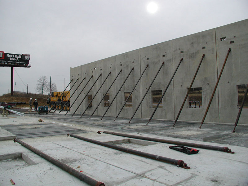
Erected wall panels braced to the slab on grade.
Slab Design
The type and location of floor slab joints, slab thickness, reinforcing, leave-out strips and concrete strength should be considered when determining if the floor slab is an adequate anchorage for the brace loads. Additionally, minimum concrete thickness for adequate anchor embedment should be a consideration when specifying the slab thickness. Thickened strips of slab, centered about where the braces will land, may be preferred in lieu of thickening the entire floor slab for wall panel temporary bracing.
When designing the slab on grade for brace loads, one must determine the wall brace component forces (horizontal/sliding and vertical/uplift) from the design wind load applied to the braced wall panels. The portion of the slab that is being relied upon to resist the brace forces must be heavy enough to resist both sliding and uplift from the brace forces. When a thickened slab is utilized, soil passive pressure may also be considered in resisting sliding.
Engineering judgment should be used when considering the portion of slab to account for in resisting brace loads. Sliding forces may be resisted by all slab areas between the wall panel and the brace anchorage to the slab; however, for uplift a smaller strip of slab should be accounted for and floor joints should be a consideration in what that strip width can be.
Bracing Connections
For connection of panel braces to the wall panel, coil inserts are usually cast into the wall panels. These coil inserts are manufactured with a plastic void plug to prevent concrete infiltration within the coil. This plug can easily be removed with pliers, after the panel has been cast, to accept a compatible ¾-inch diameter coil bolt.
Anchors used for attachment of the base of the braces can also be coil bolts attached to coil inserts cast into the floor slab, though it is often more efficient to use ¾-inch diameter concrete expansion anchors so that the braces can simply be attached where they land at the base. When using concrete expansion anchors, it is important to select an anchor that is easily removable after use so that only easily patchable holes are left in the floor. Typical tilt-up brace expansion anchors utilize an insert which is left in the concrete. The anchor itself can be unscrewed from the insert. Concrete screw anchors (usually ¾-inch diameter) are also common for tilt-up brace anchorage. These anchors are threaded to engage the concrete rather than utilizing an expandable insert to engage the concrete.
Anchors are an engineered product. Manufacturer’s information offers useful guidance for placement in the panels as well as for jobsite practices that allow the maintenance of safe working loads and safety factors.
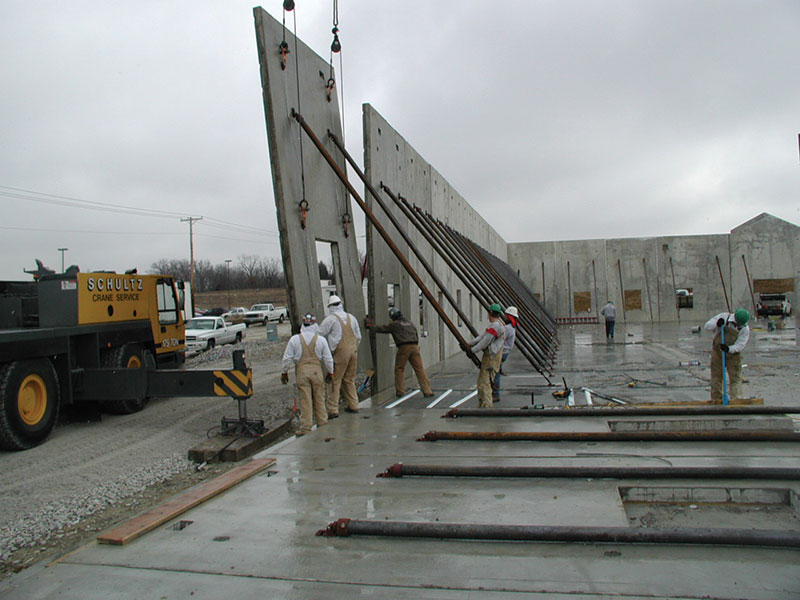
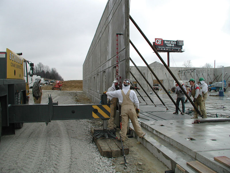
Wall panel erection in progress.
Bracing Sequencing
Bracing represents an additional element in the tilt-up process which needs to be carefully positioned and sequenced. When not planned adequately, braces can interfere with crane movement, lifting and even the placement of other braces. Brace planning efforts must consider crane access as well as each panel’s casting bed location and lifting sequence.
Braces located at interior corners also need particular attention; the panel that will be erected first needs to have its bracing placed high enough that perpendicularly placed bracing can be maneuvered comfortably below it. Openings or leave-outs in the floor slab often present problems requiring braces to be angled slightly. When floor slab openings or leave-outs are excessive, the panels should be braced to HGAs or deadmen. In corners, it is possible to brace diagonally to the adjacent orthogonal panel, if the orthogonal panel is braced adequately to stand alone until the adjacent panel is erected and braced.
For More Information
Final brace design forces should be calculated using equations set forth in ASCE 7-10 and the appropriate factors for the project. The TCA guideline includes detailed information on calculating brace forces and loads that will dictate design.
As tilt-up structures evolve away from their big-box predecessors and into architecturally unique buildings, the individualized design of temporary bracing systems becomes more important. Well-designed bracing not only helps maintain the cost and scheduling efficiencies that tilt-up is known for – it makes for a safer jobsite, as well.▪