
An Innovative High Performance Structure
The San Francisco Public Utilities Commission’s (SFPUC) new headquarters in San Francisco, California, set a new standard for high-performance structures when it opened in June 2012. The building, slated for LEED Platinum certification, is a showcase for a host of leading-edge sustainable design elements, making it one of the greenest office buildings in the nation.
In this case, the design of the structural system, including its post-tensioned concrete shear walls and construction materials, made key contributions in achieving this distinction.
The structural design followed a simple strategy of creating a highly durable and resilient structure that could be built with significantly reduced environmental impact, for a cost that was comparable to a more conventional design. In seismic country, the key to durability and resilience is designing a structure that is able to withstand a major earthquake with minimal damage. As a provider of lifeline infrastructure, the SFPUC was keen to ensure that the new facility could be easily repaired and reoccupied immediately after a large earthquake. This meant designing to a higher standard of seismic performance, which would limit structural deformations during a major shock and allowing the building to return to its original plumb position, protecting the building, occupants, contents and its systems. An innovative approach using post-tensioned concrete shear walls with composite link beams was applied to cost effectively satisfy the ambitious seismic criteria.
The high-performance seismic design of the SFPUC was based on a two-tiered criteria, which required that the structure would meet 1.0% maximum interstory drift under the design basis earthquake (DBE), corresponding to a return period of 475 years, and 1.5% maximum drift under the maximum considered earthquake (MCE), corresponding to a 2,500-year return period. Moreover, the structural system has the ability to recenter the building, resulting in negligible residual deformations. In comparison, a similar building designed to conventional standards would be allowed a maximum drift of 2.0% under the DBE, with no limit on residual drift. Major non-structural components, including the exterior cladding and the mechanical, electrical, and plumbing equipment of the building were designed to remain substantially free from damage during the DBE event. The exterior cladding system was explicitly designed to remain damage-free at the DBE event and operable with limited damage at the MCE event.
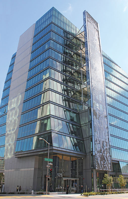
Figure 1: Completed SFPUC building.
The thirteen-story structure extends almost 200 feet above grade and comprises roughly 277,500 square feet (Figure 1). The structural system consists of a framing system of post-tensioned concrete slabs and beams supported on concrete columns and concrete core walls. The core walls, located at each end of the building, provide the building’s lateral resistance (Figure 2).
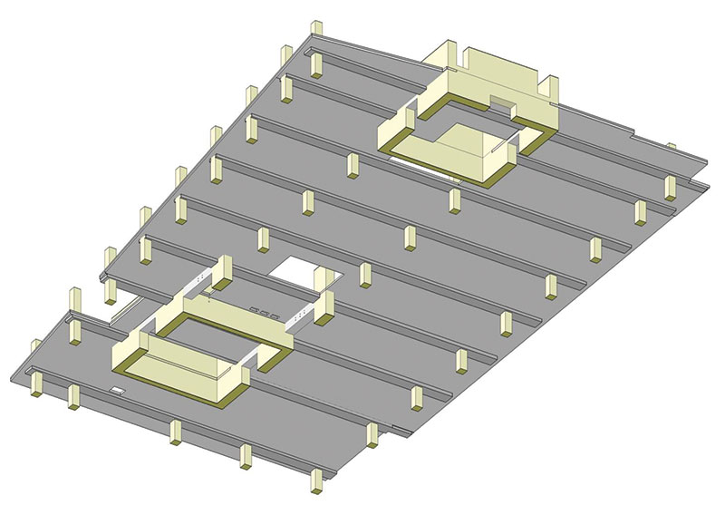
Figure 2: Schematic view of underside of floor framing and core walls.
The floor plan consists of an asymmetrical column-grid arrangement with long spans (nearly 41 feet) in the transverse direction of the building and short spans (20 feet) in the longitudinal direction (Figure 2). With this arrangement, a flat-plate slab solution would be impractical and inefficient. The structural engineers devised an efficient framing solution consisting of shallow transverse post-tensioned beams and one-way longitudinal post-tensioned slabs. The beams are typically 36 inches wide and 16 inches deep, and the slabs 6 inches thick.
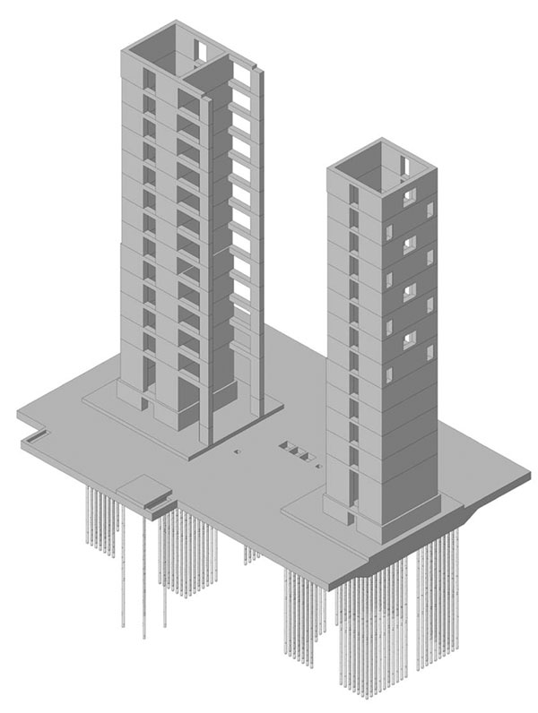
Figure 3: Isometric view of core walls.
The two concrete core shear walls are founded on a 10-foot-thick mat foundation atop micropiles embedded 65 feet below. This combination of mat foundation and micropiles are intended to resist the seismic overturning load (Figure 3). The micropiles are approximately 10 inches in overall diameter and consist of a continuous 2.5-inch diameter high-strength threaded rod that is inserted into the drilled shaft and then pressure grouted, creating piles capable of achieving high tension and compression strengths. While micropiles have traditionally been used in retrofit and transportation applications, there are several advantages to using micropiles for new construction. Their small diameter allows for a higher concentration of strength and stiffness per area, and the piles can be field tested, which allows for a more efficient design.
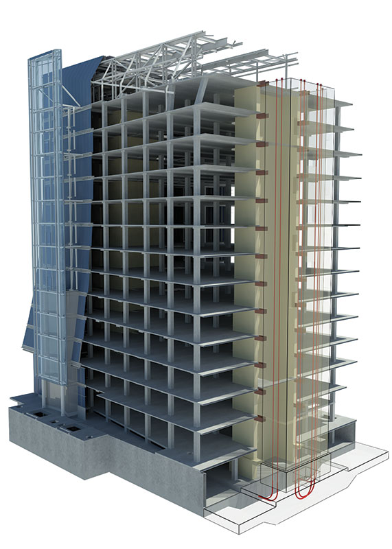
Figure 4: Schematic cutaway view of the structural system.
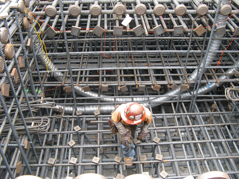
Figure 5: Mat foundation reinforcing with curved saddle for post-tensioning of the vertical post-tensioning cables.
For seismic resistance, the building uses an innovative system of self-centering concrete core shear walls and composite link beams (Figure 4). The shear wall design consists of conventional bonded reinforcing and vertical unbonded post-tensioning (PT) cables. At each core wall, the vertical post-tensioning tendons extend from the top of the core wall down through a saddle within the mat foundation (Figure 5) and back up to the top of the wall. Each of the two core walls contains eight tendon bundles that are about 400 feet long. Each bundle comprises up to 28 continuous 0.6-inch diameter strands. The vertical post-tensioning helps to provide the strength and elasticity needed to recenter the structure. Additionally, the vertical post-tensioning tendons allow for a reduction of approximately 50% in the quantity of the vertical bonded mild-steel reinforcing in the walls. This reduces labor costs and minimizes wall congestion. The cables are post-installed through corrugated steel ducts that are installed in the walls (Figure 6) and stressed at the top of the structure with a hydraulic jack (Figure 7).
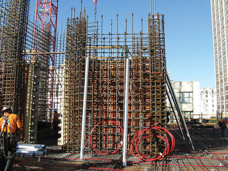
Figure 6: Core Wall reinforcing with corrugated steel ducts in walls used to post-install the vertical post-tensioning cables.
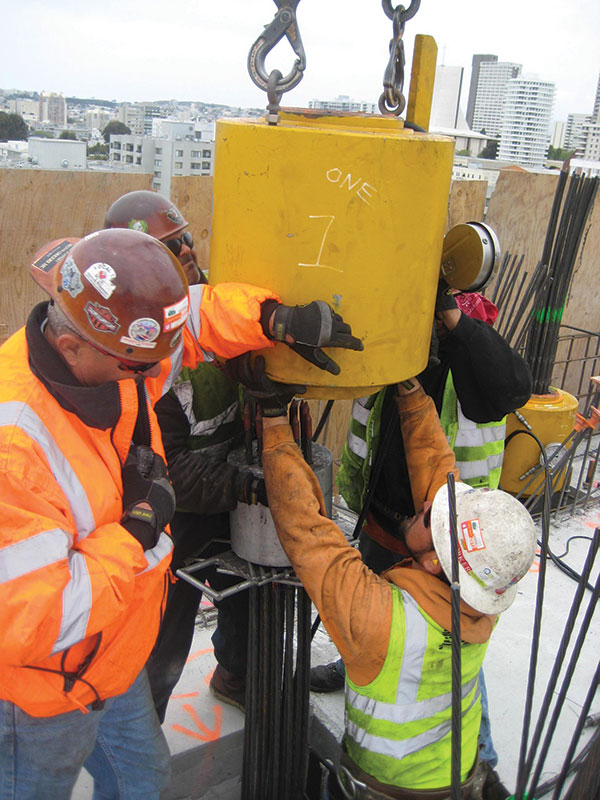
Figure 7: Hydraulic stressing jack being placed over the vertical post-tensioning tendons.
During a seismic event, the mild-steel reinforcing bars yield to dissipate energy, much like the behavior of a conventional concrete shear wall. However, the unbonded tendons remain elastic to provide a positive restoring force that recenters the structure. The walls are proportioned so that the overall flexural strength attributable to post-tensioning alone is approximately 50% of the total flexural strength of the wall.
It is critical that the walls are detailed to maintain sufficient ductility and good hysteretic behavior under the high compressive strains and repeated load reversals. This is even more important for a PT shear wall, where the PT imposes additional compressive force on the wall. In order to ensure adequate compressive strength at the wall boundary zones, the walls were constructed of high strength concrete designed to reach a compressive strength of 8,000 psi at 90 days. Additionally, special care was taken while detailing the boundary zones by adding extra confining reinforcing to extend the strain capacity of the concrete at ultimate loading. Nonlinear response history analysis was used to predict forces in critical elements, eliminate non-ductile failure modes, and ensure stable flexural mechanisms.
Figure 8: Typical shear-wall cross section.
The walls are heavily reinforced at the plastic hinge zone and first several levels of the structure. A typical wall cross section at the plastic hinge zone is shown in Figure 8. The wall consists of #10 vertical bars at both the boundary areas and at the distributed field reinforcing, with #9 horizontal shear reinforcing. At the boundary zones and areas of high compression force, the walls are confined with #5 cross ties and stirrups. In order to expedite onsite construction speed, the boundary reinforcing cages were preassembled with the stirrups installed. The horizontal reinforcing bars were lapped outside of the boundary zone to allow for easier field installation and T-heads were used to limit the congestion.
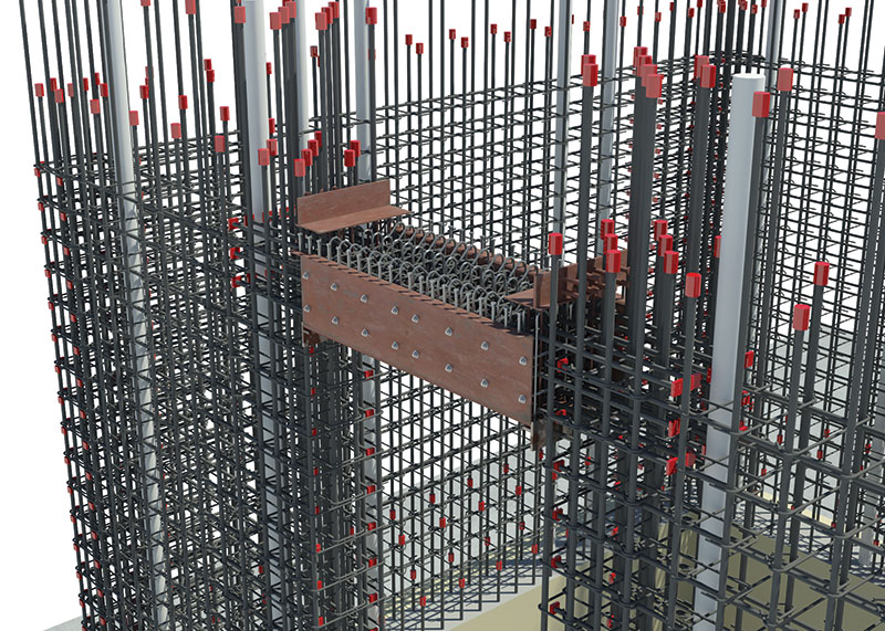
Figure 9: Rendering of the composite link beam and shear-wall reinforcing.
The composite link beams are another innovation incorporated into the structural design (Figure 9). The core walls enclose some of the building’s elevators, stairs, and mechanical shaft. The door openings into the core create coupling beams formed over the doorways. Traditionally, coupling beams are heavily reinforced, often with diagonal reinforcing, which makes them difficult to construct. For this building, the composite coupling beams were formed with a 3/8-inch thick steel jacket that was designed as both a stay-in-place formwork and beam reinforcing. The link beams are 30 inches wide and vary from 20 to 36 inches deep (Figure 10). The external steel jacket alters the behavior of the link beam in a fundamental way. Under cyclical seismic loading, the steel jacket forces a single flexural crack to form at the face of the wall, rather than allowing the distributed cracking that would be expected in a plastic hinge region of a conventional beam. Furthermore, the steel jacket relieves the compressive strains on the concrete and allows for a more ductile response with less degradation in strength and stiffness. These effects required several specialized design considerations. The longitudinal reinforcing bars in the link beams were debonded from the surrounding concrete with waxed sleeves at the joint between the steel jacket and the concrete core wall to allow an adequate plastic strain length, to prevent premature tensile fracture. In addition, embedded steel brackets were provided to mechanically restrain the link beam, ensuring a direct, reliable transfer of shear at the interface with the walls. The external steel jacket eliminates the cracking and spalling damage that would otherwise be expected with a conventional coupling beam, thus minimizing the need for extensive post-earthquake repairs.
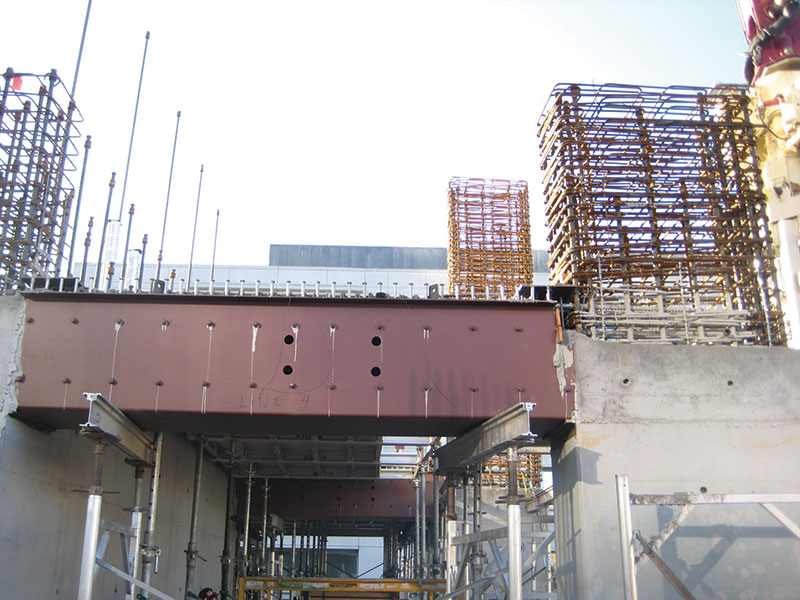
Figure 10: Link beam steel jacket.
As the SFPUC was designed to achieve LEED platinum status, it was important for the team to address the environmental impact of the concrete. Through a collaborative partnership between Tipping Mar, the general contractor, and the concrete supplier, custom low-cement concrete mixtures were developed that were shown to reduce the carbon footprint of the material by 50% overall. The high-strength green-concrete mixes were tailored for each application, and specified the replacement of Portland cement by up to 70% using a combination of slag and flyash.
The SFPUC headquarters project embodies the spirit of the institution it serves. It represents a significant advancement in how office buildings are designed and built. In this spirit, Integrated Project Delivery (IPD) was selected for the design and construction of the building. This delivery method allows for a collaborative relationship between the owner/developer (SFPUC and SF DPW), the contractor, and designers, whereby the risks and rewards are shared. This building’s design and construction is a demonstration and guiding example of how leading-edge technologies and innovations can come together to fulfill an ambitious civic vision of sustainability.▪
The building was designed through the collaboration of KMD Architects and Stevens and Associates Architects, with Tipping Mar and SOHA Engineers performing the structural engineering design. Webcor Builders was the general contractor and Central Concrete was the concrete supplier for the project. San Francisco’s Department of Public Works was responsible for managing the project.
All graphics courtesy of Tipping Mar.