
From Planning to Completion
It is not unusual to create an opening in existing floors during building renovations and alterations. A new opening may be used for stairs, an elevator shaft, a duct penetration, skylights, etc. In order to execute a feasible modification and maintain the existing building’s structural stability, a qualified structural engineer should be involved during the initial planning phase. With varied knowledge of floor construction types and extensive experience in structural evaluation and strengthening, the structural engineer can present valuable suggestions regarding the selection of opening locations, construction feasibility and possible strengthening options. This article presents a typical procedure to create openings in existing floors, and discusses some practical issues.
Typical floor construction types.
Effects of an opening to existing concrete slab.
Planning of an Opening
Where to make an opening in a floor sounds very simple – just put it where it should be – but this is true only for new construction, when all kinds of openings can be accommodated using various structural design methods. However, it is a very different situation to create a new opening in an existing floor where construction is constrained by surrounding elements that are part of structural systems. An improper location of the opening may lead to a large amount of renovation work, making the project uneconomical and perhaps even rendering it impossible to develop a feasible structural solution.
A good plan for an opening is half the battle; the first and primary rule of thumb is to avoid locating the opening across major existing building elements – i.e., girders, columns and walls – to limit the affected zone, in regard to altering the structural continuity of the building. Due to the many possible types of construction that may be encountered – such as a masonry arch floor, a steel-wire catenary floor, and modern beam/plate floor types that consist of wood or light gauge steel joists, steel beams, precast concrete planks, cast-in-place concrete slabs, etc. – a thorough understanding of the existing building type and floor system must be obtained. A review of existing construction documents, if available, will provide basic information; however, physical inspections and probes are essential to determine as-built conditions. Based on the findings of a comprehensive study of the floor system, the location of the openings can be adjusted and finalized.
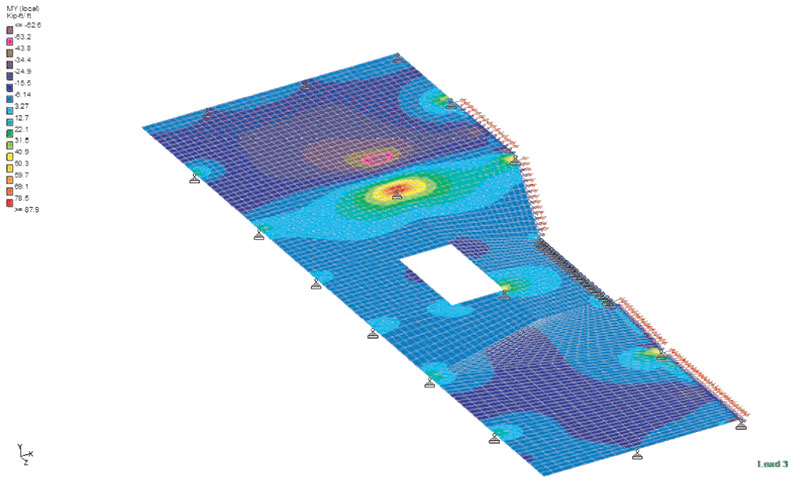
Finite element analysis of a two-way slab with opening.
Evaluation of Existing Structures
Once the opening is located, relevant existing floor structures must be carefully assessed. The proposed opening may affect existing floor structures in one or all of the following ways: (1) the design live load is increased at the new stair landing area, thereby overloading adjacent portions of the floor; (2) the original structural design assumptions (e.g., continuous beam, arch action, etc.) will not be satisfied after the opening is made; (3) in the case of a T-beam, the flange is partially or completely removed at the opening side, thereby reducing flexural resistance and stiffness; and (4) structural capacities are undermined when floor reinforcement is eliminated or cut off when creating an opening in a concrete slab. Actual effects on any existing floor structures are dependent on its construction type.
Masonry arch floor construction, made of hollow tiles or terra cotta, was very popular for buildings constructed from the late 1800s to early 1900s. The segmental masonry pieces work together, and span between adjacent steel beams by using arch action with tie rods to resist the tension thrust. Once some segments are removed for an opening, the corresponding arch action will be lost. The remaining pieces will not be stable and should be removed. If a tie rod is to be cut off, it may be necessary to install a new steel beam beforehand, unless field conditions suggest that the required tension thrust is properly resolved by the stability of the adjacent spans or bays.
Steel wire catenary floor construction became popular in 1910 and disappeared gradually after World War II. The steel wires are draped and continuous over steel beams so that gravity loads are sustained by the tension in the suspended wires, which are encased in cinder concrete mainly for the purpose of fire protection. When an opening is to be made in this system, it is inevitable that some wires will need to be cut, which will disrupt the continuity and stability of the system. In order to stabilize the floor at adjacent spans, proper anchorage of the cut wires must be designed.
For floors consisting of joists or floor beams, an opening can usually be framed simply by installing new transfer beams, which form the perimeter of the new opening. These transfer beams can support the floor joists/beams at the opening, and distribute design loads to adjacent girders, columns and walls. Evaluation of the existing structures under new loading conditions is straightforward but essential.
An opening in precast plank floors can be framed by the installation of steel headers. The new members will redistribute the design loads to adjacent planks in accordance with the guidelines presented in the PCI Design Manual, and the relevant planks should be evaluated for design loads per the renovation plan in addition to the distributed loads from the header. Moreover, the remaining parts of planks with proposed openings must be reassessed to determine whether the development length of the residual strands, from the cut edge to the point of maximum required moment, is still valid for the full specified tensile strength. Otherwise, the residual flexural resistance should be adjusted.
A reinforced concrete slab may be treated as either a one-way slab or a two-way slab based on the aspect ratio of the length in the long direction to the width in the short direction. A one-way slab is considered when an aspect ratio of at least two is realized. A one-way slab will function like a beam in the short direction, continuously spanning over supports such as T-beams or walls. However, continuity will be interrupted at the proposed opening and the slab’s required design moments at adjacent spans will be increased. In addition, the T-beam’s flange will be partially or completely removed at the opening side, weakening the T-beam’s design strength and stiffness and perhaps even inducing torsion effects.
A two-way slab is considered when an aspect ratio of less than two is realized. It supports the design loads in both directions on its column strips and middle strips simultaneously. When an opening is to be made, part of the slab’s column strip and/or middle strip is removed, and relevant reinforcement is cut off. To calculate the required moment capacity after creation of the opening, the equivalent frame method specified in ACI 318 is still applicable as long as the assumptions are satisfied. However, a finite element analysis is a better way to find relatively more accurate solutions to the design moments and maximum deflections concerned.
In a finite element model, at least two adjacent floor spans around the opening must be considered. Load-bearing walls and additional spans of the floor slab may be simplified as proper boundary conditions. To calculate the residual flexural resistance, the actual amount and placement of steel reinforcement in the slab must be investigated and verified by using non-destructive test instruments such as ground penetration radar. By comparing the required design moment to the residual flexural resistance, it can be determined if strengthening of the slab due to the opening is necessary. It should be noted that if an opening is located completely within the “slab” portion of a two-way slab–i.e., not located across column strips – then the resulting opening may not require reinforcement.

New transfer beams around the opening.
Strengthening Design Options
An efficient strengthening method is to install new transfer beams to frame an opening. The new beams will take design loads on residual floor structures around the opening and distribute the loads to adjacent existing girders, columns or walls. The new beams can often be framed flush with existing floor structures and totally hidden inside finish ceilings. Due to its simplicity and efficiency, the transfer beam is generally the first choice to strengthen an opening whenever possible.
However, for certain floor construction types like concrete slabs, new transfer beams cannot be framed flush, but must instead be installed underneath the slab to connect with adjacent existing columns or girders. When floor headroom and aesthetic appearance are of paramount concern, externally bonded or bolted plate methods may be employed.
For this popular and economical strengthening approach, the steel plates are considered to be tension reinforcement placed on the surfaces of concrete slabs. The plates are sized based on the required design moments under superimposed loads. The bonding agent (e.g., epoxy resin) and anchor bolts provide the surface shear stresses needed for composite action between the plates and the concrete. When it is necessary to strengthen the slab in both directions, the intersection of steel plates must be properly detailed. Some practical solutions include encasing the steel plate in one direction into the concrete slab or pre-welding the steel plates in both directions at the intersection points.
Externally bonded/bolted steel plates method.
Peer Review and Construction
Prior to making a new opening in an existing building, a construction permit is often required, for which an independent structural peer review is mandatory per the building code. If possible, the building’s original structural engineer of record, who has the greatest knowledge of the existing structural design, is the most appropriate design professional to serve as the peer reviewer. The peer review involves confirming the renovation design criteria, attesting to the general completeness of the construction documents, and verifying the new design in accordance with building codes and relevant industry standards. All comments by the peer review must be answered and manifested in the final construction documents.
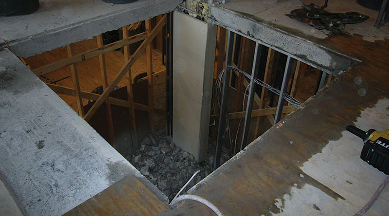
The construction itself begins with shoring installation to support all interim design loads during construction. The shoring often simply consists of 2x stud walls around the proposed opening. It may be omitted if floor structures are to be properly strengthened, as per the design, prior to making the opening. An overcut should be prohibited; marking opening edges and drilling holes at the corners is good practice to prevent this. Diamond blade saws are commonly used to cut existing floors. After the opening is made, fire protection should be applied on new steel members either by spray or as part of a rated ceiling assembly.
Ground penetration radar image of slab reinforcement.
Summary
Each building is unique, and there is no one universal method by which to create openings in every building type. In this article, we have discussed basic principles that should be respected when considering a proposed opening. There will arise many deviations when facing actual projects. A structural engineer, with appropriate knowledge and experience, will be required to coordinate thoroughly with the owner, architect and other relevant parties in order to evaluate and implement an appropriate and economical proposal, design and construction for a new floor opening.▪