
Part 2: Solutions
Part 1 of this series discussed the investigation of an existing timber-framed, multi-story building, that is over one hundred years old, and the resulting evacuation of the occupants due to an unsafe condition at the main support columns of the building. This installment discusses the nature of the deterioration observed and the solutions considered for repair.
The deterioration and damage of the timber columns could be attributed to two primary causes: moisture and insects. It was unclear to what extent each column base had deteriorated, but visual observations indicated that at least three of the eight affected primary wood columns had lost almost all of the cross-sectional area at the base below the top of the basement slab on grade. Partial removal of the concrete slab from around the column bases at the remaining five locations, to determine the extent of deterioration, was not possible because the slab in the same immediate area provided the only support for the 3×12 side plates.
This restriction occurred because it had been observed that, as the deterioration progressed in the main building columns, the load had been transferred to the 3×12 side plates via the existing through bolts. As a result, the 3×12 side plates were beginning to exhibit localized crushing at their bases, which allowed the building to settle vertically. The resulting deflection subsequently allowed the second floor framing to move and rotate as the columns dropped unevenly into the voids left by the deteriorated timber. Continued vertical movement was also allowed by the deterioration of the column side plates; however, at the worst areas of deterioration of the 3×12’s, masonry piers had been previously installed adjacent to the building columns (Figure 1). Unfortunately, these supplemental supports were only able to engage the first floor framing, rather than assist with the transfer of the main building column loads from any of the other floors above.
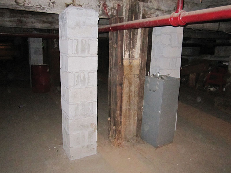
Figure 1
Solutions to the observed conditions were limited due to the lack of continuity of the beam-to-column connections throughout the building, and the unstable nature of the basement deterioration. One option that was considered initially involved shoring the columns from the basement slab up to the roof, removing the columns, and then replacing them with structural steel. This conventional solution was quickly ruled out after it was determined that it was not practical to remove or shore around the large first-floor kilns that were located immediately adjacent to the columns. In addition, it was also determined that the third- and fourth-floor residential plans were laid out such that bathrooms, closets, kitchen countertops and other finishes would have to be removed in order to facilitate the temporary shoring and permanent replacement of the building columns.
A second option that was considered involved strengthening the second-floor beams at the joint above the first-floor columns so that the same beams could act as transfer girders to support the upper floors, via new columns that would be installed down to additional foundations through the first floor and basement spaces. This option was also ruled out because of the precarious rotated condition of the second-floor beam, corbel and column joint, and the resulting difficulty of installing adequate strengthening of the second-floor beams through this same joint directly above the existing adjacent kilns.
It was eventually decided that temporarily shoring of the timber columns in the basement using miscellaneous steel plates and channels down to the slab on grade should be implemented until a more permanent solution could be established. Ultimately, it was determined that the best solution involved developing this temporary shoring into a permanent fix. Initially this approach involved using through bolts to attach the steel reinforcing to the sides of the column in order to engage the wood, and transfer the entire reaction down to the slab on grade by distributing the load over a large area via steel grillage. However, due to the extensive damage to the wood columns for most of the basement height, it was determined that the use of through bolts would require extensive epoxy injection in order to make the timber sound enough to engage the bolts properly. Because there was a concern that the extent of epoxy injection might result in localized failure of the adjacent deteriorated wood, and potentially cause complete failure of the column, this alternative was discarded.
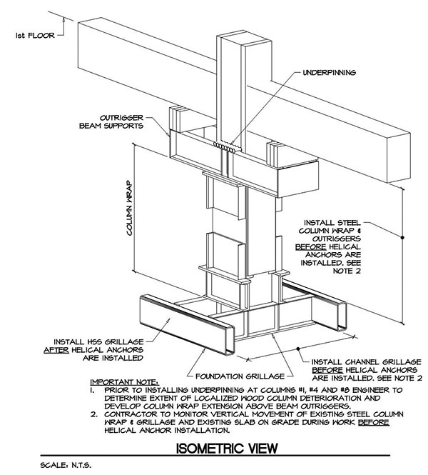
Figure 2
As a result, the final permanent solution evolved into an approach that involved abandoning the deteriorated timber column in place. This was accomplished by designing the steel reinforcing as a metal jacket built completely around each column using various steel plates and channels (Figure 2). The jackets were prefabricated in such a way that they could be brought to the site in two pieces and then erected and bolted together around the column. Bolting the jacket assembly together was preferred in order to avoid field-welding as much as possible, due to the age and condition of the timber in the basement. The steel jackets that encapsulated the timber columns were supported at the base by a series of steel channels that transferred the vertical loads on to additional steel channel grillage, which were designed to span continuously over the top of the slab on grade parallel to the column centerline. The slab on grade was analyzed as an unreinforced section, and the steel channel grillage was arranged and extended in such a way that the modulus of rupture of the unreinforced concrete slab was not exceeded under the full column design load. There were two critical assumptions that were made as a part of the grillage design and slab on grade analysis:
- The slab was a minimum of six inches thick.
- The soil had an allowable bearing capacity of at least 3,000 pounds per square foot.
Both of these assumptions were to be verified prior to the installation of the grillage.
The final successful approach to avoid through-bolting of the jacket to the wood columns involved the following solutions. First, because the first floor beams did not attach directly to the building columns, structural steel channel outriggers were cantilevered from the top of each jacket to support the beam reactions that were being resisted by the 3×12 side plates. Timber blocking was placed between the top of the channel outriggers and the bottom of the existing beams, in order to provide an adequate load path mechanism to the steel jacket for the first floor framing. The critical method for transferring the primary column load to the steel jacket involved the use of a series of 1½-inch-diameter steel rods that were drilled through the top of the column just below the first-floor framing. Locating the through rods at the top of the columns was determined to be a safer approach than the initial through-bolting scheme over the entire height of the columns in the basement, because the extent of existing deterioration of the wood was much less at the top of the columns than that observed over the lower portion.
Figure 3
The methodology for installing the rods was similar to that used for underpinning an existing foundation, in that the rods were installed in a logical sequence that allowed for the progressive transfer of the column load to the steel jacket (Figure 3). This was accomplished by first pre-drilling a pilot hole, inspecting for deterioration of the wood, injecting epoxy as required to stabilize the wood, and then drilling through the timber column and installing the steel rods one by one in the specified sequence. Pre-drilling also enabled the detection of interior deterioration by noting any variations in the drilling resistance encountered. The rods were placed side-by-side such that, once all of the specified number of rods were in place, the load from the column would be entirely supported by the rods and therefore transferred to the steel jacket, effectively abandoning the timber column below the rods.
Part 3 of this series will discuss the impact of the findings of a soil investigation that resulted in the need to develop alternate foundation solutions for the support of the steel jacket, as well as repairs that were required in addition to the column jackets.▪