
5 Steps to Improved Steel Joist and Deck Design
Steel joist and deck systems are already an efficient means of construction, but there are ways an engineer can design these systems more efficiently and cost effectively. Techniques include designing support framing to maximize deck strength utilization, selecting seat sizes to accommodate long joist top chord extensions, detailing of moment and axial connections in rigid frames, improving detailing coordination, and deciding between ASD and LRFD design methodologies.
Optimizing Joist Framing to Maximize Deck Utilization
There are two ways to specify the loading for joists. Either choose a standard Steel Joist Institute (SJI) designation with its accompanying total load (TL) and live load (LL) capacities, or specify all applicable design loadings with a base TL/LL designation. The latter specifying method allows for the most economical joist design. The joist will be designed specifically for the needs of the project. Deck design, however, only allows for standard designations to be chosen. The properties and capacities listed in manufacturer provided load tables cannot be changed, disregarding base material changes. The best way to maximize the utilization of a chosen deck size and section is to utilize the allowable loads and maximum construction spans indicated in the deck tables. In doing so, the specifying professional is taking full advantage of the deck strength, resulting in fewer joists, less steel to buy, lower transportation costs, and shorter erection time. For example, consider a given design load of 25/30 psf, dead/live load respectively, a joist span of 50 feet, a girder span of 40 feet, and a common joist spacing of 5 feet. Using the economic joist tables (Figure 1) we get 30K10 as an economical joist. Now if we re-orient the joist while staying within the maximum construction span for the deck, and try a 6-foot 8-inch joist spacing, an economical joist is 32LH07. The entire bay weight for the 5-foot joist spacing is 11,980 pounds and the entire bay weight for 6-foot 8-inch joist spacing is 9,960 pounds. This yields a 16.8% weight savings and an estimated erection savings of 22%.
Figure 1. Excerpt of economical joist design table.
Another consideration is to evaluate the capacities of the roof deck for higher yield strengths for given spans. For example, standard B deck has a minimum yield strength of 33 ksi, though materials with higher yields are available. American Iron and Steel Institute (AISI) material standards limit the maximum design yield stress to 60 ksi. On larger projects, instead of increasing deck gage, engineers should consider contacting the deck manufacturer for the option of specifying a higher yield strength. In most cases, a stronger steel deck will be more economical than a thicker steel deck gage of lesser yield strength. For example, consider a roof design load of 100 psf, a triple span condition, and a 6-foot joist spacing. Typically a B20 deck section would be specified with the standard 33 ksi yield strength, but when considering increasing the yield strength to 40 ksi, a B22 deck would be sufficient. If this option is chosen, the material requirements must be noted clearly on the contract documents so the deck coil can be properly sourced for the minimum required yield and carried out through the entire project. The use of non-standard material strengths is most effective in situations where the deck section with standard material strength is almost sufficient in capacity, but still falls short. Non-standard yield strength selections may result in additional cost and/or additional required scheduling time. The impact on both cost and schedule is greater on smaller projects than it is on larger projects.
Another deck sourcing option for larger projects is the use of alternate special deck gauge. For example, a 500,000 square-foot building using 20 gage B deck has an approximate weight of 490 tons. By using 21 gage B-deck instead, the approximate weight of the deck is lowered by 40 tons (now to 450 tons total). As with non-standard material strength requirements, non-standard gages may result in additional cost and/or additional required scheduling time, but result in an overall lower construction cost. Coordinating with a deck manufacturer early in the design process will minimize these issues.
Selecting Appropriate Joist Seat Sizing
Top chord extensions (TCXs) are a common feature in most structures. They are excellent elements for spanning small bays adjacent to the main spans, and for providing a cantilevered ledge over the edge of a building. TCX’s tend to be fairly unfavorable at shallow and longer lengths. The SJI K-Series standard seat depth is 2½ inches and, therefore, joist top chords are limited to angles with 2½-inch legs or less. The specifying professional can simply verify acceptable load and length limits by referring to the SJI standard load table for joist top chord extensions (Figure 2). In Figure 2, notice that as the length of the extension increases, the load per foot capacity decreases. If the specifying professional’s design criterion falls outside of the limits listed in the SJI table, a change to the seat design will need to be coordinated with the joist manufacturer. Design loads may be achieved by simply increasing the seat depth. K-Series joists are designed for a maximum allowable uniform load of 550 plf. Per the SJI table, for a 4-foot 6-inch span, the TCX can support a 550 plf load, though this is possibly not the most efficient design. For example, consider a 30K10 joist with a 50-foot span and a TCX to be designed for 550 plf. If the 30K10 joist has a standard 2.5-inch seat depth, the total joist weight will equal 810 pounds. This same joist with an increased seat depth of 3.5-inch will have a total weight of 710 pounds. With a 5-inch seat depth, the weight is reduced further to 695 pounds. Using the deeper seat depth of 5 inches results in an approximate 14% weight savings. With a shallow seat depth, the size of the top chord (TC) angles are controlled by the loading on the TCX, not by the loading of the main span. The deeper seats allow for the main span of the joist to control material sizing of the TC. See Figure 3 for general seat schematics and section properties.
Figure 2. SJI standard load table for top chord extensions.
Figure 3. Joist seat size examples.
Detailing of Moment and Axial Connections in Rigid Frames
Using joists and joist girders as part of a rigid moment frame is common. It can often provide an economic advantage to the project as compared to wide flange beams in moment frames, or using steel braced frames or concrete shear walls. The axial loads induced by the rigid moment frame develop secondary moments (M=+/- P x Ecc.) in the joist chords, especially when the load path is through the joists seats and column connection. Joist and joist girder chords have a relatively low moment capacity. When these eccentric loads become large, chord designs will generate larger sections and/or expensive chord reinforcement. The most economical way to design for these induced axial loads is to provide a direct load path from the chords to the support or to another abutting member. The alternate load path will reduce or eliminate the eccentric moment in the joist or joist girder chord. It is preferred that the specifying engineer design the tying mechanism between the chords and/or support. In doing so, the specifying engineer will have more control over his or her design, require less coordination with the joist manufacturer and obtain the most economical joist or joist girder. Some example connections are indicated in Figure 4. Also, visit www.steeljoist.org/design_tools to access free moment connection design tools, provided by the Steel Joist Institute.
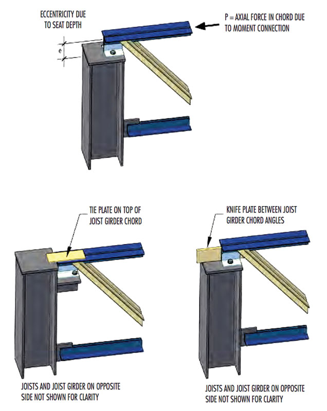
Figure 4. Axial load tie examples.
Benefits of Improved Detailing Coordination
At present, there is a need for more communication between suppliers, engineers, architects, and fabricators. Often, structural contract drawings are incomplete. Drawings are missing dimensions and loads, have “canned” notes which do not apply to the project, or have contradicting requirements in the notes and project specifications. These and other issues can lead to project delays, contingency fees, and occupancy income loss. The RFI process, which must handle the drawing issues, is intended as a valuable way of opening communication, expediting fabrication and delivery, and preventing additional project costs. When the joist manufacturer is brought into the design process early in a project, the specifying engineer can make use of the engineering experience of the manufacturer to create the most efficient joist and deck system. This increased collaboration fosters increased communication between the different parties on the project and allows for the manufacturer to think creatively about engineering from the standpoint of cost-reduction.
A major subject of communication between the project designer and the joist manufacturer is the issue of non-uniform loading. Some common non-uniform loadings include snowdrifts, roof top mechanical units, screenwalls, cranes, folding partition walls, fall arrest systems, fire sprinklers, parapet bracing, and wind uplift. The best way to communicate special loadings is to include them in load diagrams with appropriate “Tag End” or gridline labels. Using well-labeled and dimensioned loading diagrams clearly communicates to the joist manufacturer what loads to design for, and where to exactly locate them.
Commonly, the final positions of non-uniform loads are not known until late in the production schedule. In these situations, there are several techniques that can be used to allow the joist manufacturer to properly design for the final loading. A concentrated load can be applied in a zone across the joist. The load would be specified with a location dimension and an accompanying +/- length dimension. The joist chord would need to be reinforced in the field at the final load location with a field vertical if the load did not land at an existing panel point. If the location is not known at all, the concentrated load can be specified to land at any panel point or at any point along the chord. A load located at any point would not require field panel point reinforcement; however, if it is located along the chord, it would increase the section size of the loaded chord to resist local bending. For non-uniform loading, the more location information that is provided, the more efficient the joist design can be.
Roofs will typically require design for snowdrift and uplift forces. Supplying the joist manufacturer with net uplift drawings instead of “component and cladding” loads will save detailing time and shorten the approval process. Clearly indicating snowdrift loads on the drawing, and whether the drift loading has already been included in the design, will also save time.
If moving loads from cranes or folding partition walls need to be specified, multiple load cases and load locations must be provided to the joist manufacturer to allow for the proper design of the joists. For crane loads, it is very important to include the Crane Manufacturers Association of America classification (A, B, or C) or the estimated lifetime loading cycles, the impact loading, and the operating method of the crane in question, as this information is required for the fatigue design of the joists. When considering joists supporting dynamic loads such as these, it is also important to specify whether any special camber or deflection requirements are required, as they can change joist size requirements significantly.
Coordinating information about loading early and completely to the joist manufacturer will speed up the design process and limit the extent of RFIs on a project.
ASD or LRFD Design
For some time now, the Steel Joist Institute has provided ASD (Allowable Strength Design) or LRFD (Load Resistance Factor Design) load tables. The specifying professional should indicate on the contract drawings which design method was chosen for the design. When specifying the LRFD method, it is necessary to provide factored loads on the drawings, as well as to state that the loads are factored. When specifying a girder, remember to provide the total factored load and designate the girders with “F” instead of the “K” designation, which will help distinguish that the load has already been factored. For example, a girder designation in ASD would be 50G8N10K and the same designation in LRFD would be 50G8N15F.
Joists built to the same SJI joist designation will have the same weight, regardless of which design methodology was used to select them. The required SJI joist designation, however, may differ for the same required TL/LL loading depending upon which design methodology is used. If a TL/LL designation is specified, any joists could see savings. The simplest way to determine which design method will provide the most value is to examine the ratio of dead loads to live loads. For exceptionally light dead loads, an ASD design is more than likely to produce a lighter joist. When the live loading is less than three times the dead loading, the LRFD design method would produce the lighter joist. For example, consider a joist with a 50-foot span, 6-foot spacing (roof application), a DL of 20 psf (120 plf), and a LL of 30 psf (180 plf). Using the LRFD design method, the required factored load capacity for the joist is (1.2*DL+1.6*LL) = 432 plf. For this span and loading, a 30K10 would be the most economical joist (Figure 1). The self-weight of a 30K10 is 11.5 plf. Using the ASD design method, the required service load capacity for the joist is (DL+LL) = 300 plf. For this span and loading, a 30K11 would be required (Figure 1). The self-weight of a 30K11 is 13.1 plf, which is 1.6 plf heavier than the LRFD chosen 30K10. An important note to remember when deciding on a design method is that the methodology must remain consistent across all joists on a project. The cost savings across the entire project must be considered, not the individual savings on a small area.
Summary
These techniques, when used individually, can have small impacts on the economy of the steel joist and deck system. However, when used together and used often, the cascading savings will lead to shorter project schedules, less re-work, fewer joists to erect, and lower material pricing. Partnering with a joist and deck manufacturer early in a project will bring in more expertise and experienced engineers who can help you design the most efficient joist and deck system possible.▪