Adjusting for Changes in Mass and Stiffness
Structural design of tall buildings is driven by forces of nature, including wind and earthquakes. As buildings get taller, wind-induced dynamic response dictates the design of the lateral system to meet both serviceability and survivability limit states. Structural engineers rely upon wind tunnel consultants to determine equivalent static loads (ESL) and top floor accelerations (TFA). This becomes increasingly important for tall and slender towers where across-wind effects dominate. After the building has been tested, the structural design continues to develop, resulting in changes to the mass and/or the stiffness. To quantify the increase or decrease in ESL and TFA, the structural engineer needs to send an updated set of dynamic properties to the wind consultant for a new cycle of post-processing. This article presents an alternative to this process in the form of design charts that enable the design engineer to adjust ESL and TFA for changes in mass and/or stiffness. The interaction between the design team and the wind consultant could then be saved for major design milestones to confirm wind loads and responses.
How does Wind Excite a Tall Building?
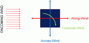
Under the action of wind, tall structures are loaded simultaneously in the along-wind, across-wind and torsional directions as shown in Figure 1. The loads can be broken down into static loads due to mean wind pressure and dynamic loads due to fluctuating pressure. The fluctuating pressure induces two distinct responses; a low-frequency background component and a resonant component at the fundamental frequency of the structure. While all three sources contribute to the along-wind loading, only the fluctuating wind pressure – the background and resonant components – results in the across-wind and torsional loadings. TFA is a result of the resonant response only. The mean and background components are primarily dependent on the building geometry and the turbulence environment, while the resonant response, in addition to geometry and turbulence, depends on the structure’s dynamic properties; mass, stiffness and damping.
Does the Building Code Address All Three Components?
ASCE 7 provides a comprehensive treatment of the along-wind response of flexible structures based on the Gust Factor Approach. However, ASCE 7, similar to many codes and standards, provides no guidance on the across-wind response and limited guidance on the torsional response.
Are There Any Tools to Estimate Across-Wind Response?
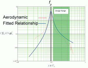
Over the years, wind tunnel testing has provided valuable aerodynamic data for the across-wind response. The across-wind spectra exhibits an evident peak around the Strouhal number, as shown in Figure 2. The Strouhal number is measured in terms of non-dimensional reduced frequency, f* = f x B/UH, where f is the natural frequency of the building, B is the building width perpendicular to the approaching wind and UH is the mean hourly wind speed at the building height. The structural response peaks when f* matches the peak frequency (Strouhal number), fp. Tall building designers always tune the structural system to have a reduced frequency, at the strength level wind speed, that is greater than fp as shown in Figure 2.
Relationships have been developed using curve-fitting to predict the across-wind Power Spectral Density (PSD) as shown in Figure 2, as well as the Root-Mean-Square (RMS) of the base moment coefficient. These relationships take into account the turbulence environment, building aspect ratio and building side ratio. In particular, the model by Gu & Quan is reported to produce a good fit for a wide range of buildings and turbulence environments.
How are Across-Wind Models Used?
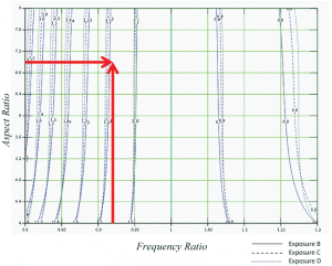
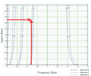
Non-dimensional across-wind models can be used to compute wind-induced response of any structure having architectural features and a turbulence environment that are within the limits of the model. The model by Gu & Quan was calibrated for aspect ratios of 4 to 9, side ratios of 0.5 to 2 and four different wind exposures. Using this model, the upper-bound ESL adjustment factor chart is developed and is shown in Figure 3 for buildings with a side ratio of 1.0. The adjustment factor is plotted vs. the frequency ratio (original frequency / new frequency) on the horizontal axis and the aspect ratio on the vertical axis. Similarly, a lower-bound ESL adjustment factor chart is shown in Figure 4. Figures 3 and 4 indicate that the base moment decreases with an increase in the natural frequency of the structure, but increases more rapidly with a decrease in the natural frequency. This is consistent with the increased slope of the PSD as f* moves toward fp. The charts show a slight dependency on the wind exposure.
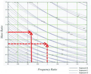
A TFA adjustment factor chart is shown in Figure 5 for buildings with a side ratio of 1 and an aspect ratio of 7. The adjustment factor is plotted vs. the frequency ratio (original frequency / new frequency) on the horizontal axis and the mass ratio (original mass / new mass) on the vertical axis. Figure 5 indicates that TFA decreases with an increase in frequency and/or mass of the structure, as expected. The dependency on the exposure is insignificant.
Design Example
Consider a 76-story residential concrete tower located in Los Angeles, California. The overall height of the building is about 260 meters (858 feet) with a square floor plan roughly 37 meters (121 feet) on each side. The wind exposure category is close to B as defined by ASCE 7. The lateral system consists of a reinforced concrete shear wall core with rigid outriggers (in one direction), and the gravity system consists of concrete flat plates supported by concrete columns. The resonant wind response, reported by the wind tunnel consultant, was mainly due to across-wind effects, with TFA of 18 milli-g. During the design development phase, the design team learned that the original target strength of 10,000 psi for concrete would not be achievable using local aggregate. The owner asked the design team to reevaluate the structural system using a maximum concrete strength of 7,000 psi. This concrete strength reduction resulted in a stiffness decrease of about 16%, which then reduced the natural frequencies by approximately 8%. Figure 5 shows an increase in TFA of about 12%. From a strength point of view, the force increased by approximately 12-18% based on Figures 3 and 4. Increasing the flexural strength of the shear walls was not an option due to seismic considerations in shear.
The design team decided to add post-tensioning to the concrete flat plates in order to reduce their thickness by about 20%. This reduced the generalized mass by about 15%, restoring the building’s original fundamental frequencies so that the wind strength design could remain unchanged. However, the mass decrease also resulted in a TFA increase of about 20% per Figure 5. To deal with this, the design team proposed a damped outrigger system (90° to the rigid outriggers) to increase the sway mode equivalent damping ratio from 1% to 3% (in one direction), thus achieving TFA of 13 milli-g.
Conclusion
Changes in mass and stiffness during design affect a structure’s dynamic response to wind effects, which in turn require revisions to the associated equivalent static loads and top floor acceleration. Charts such as those in Figures 3, 4 and 5 provide a “quick and dirty” tool to estimate the impacts of such changes on strength and serviceability. However, confirmation from revised wind tunnel post-processing is still strongly recommended at design milestones. Engineered damping provides an economical alternative to meet serviceability (and possibly strength) design requirements, even at the final stages of structural design.▪

