
Fort Jefferson National Monument is located in the Dry Tortugas, a group of sand bars 70 miles west of Key West, Florida. This great pile of 16 million bricks surrounding coral concrete cores was originally intended to defend a harbor for ships of the US Navy, allowing the naval forces to control shipping through the Straits of Florida and, ultimately, to control trade through the Gulf of Mexico and into the Mississippi River. The fort occupies over seventy percent of Garden Key, one of the larger islands of what is now Dry Tortugas National Park (Figures 1, 2 and 3).
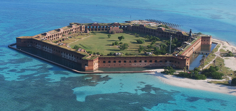
Figure 1: Fort Jefferson, in the Dry Tortugas, is in a serenely beautiful setting, accessible primarily by ferry and seaplane.
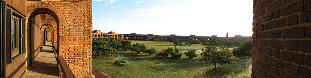
Figure 2: The fort is reported to be the largest masonry structure in the western hemisphere.
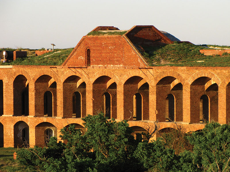
Figure 3: Arches and vaults composed of 16 million bricks surround inner cores of coral concrete.
The history of the construction of the fort is bewildering. Noted in 1829 by U.S. Navy Commodore John Rodgers as an ideal location for an advance post for the defense of the Gulf Coast, the study and design process occupied the next 17 years, culminating in 1846 with the start of construction. The fort was still not complete in 1865 at the end of the Civil War, by which time the invention of rifled cannon had made the fort itself obsolete. The fort was used, unfinished, as a Federal prison during and after the Civil War. It still remains unfinished today, serving as a marine research station and a National Park.
Now accessible primarily by seaplane and ferry, the fort that once housed Dr. Samuel Mudd, imprisoned for tending to John Wilkes Booth’s broken leg, sees up to a few hundred visitors a day who take either a 45 minute seaplane ride or an almost three hour ferry ride from Key West to tour the casemates, snorkel among the sergeant majors and parrot fish, and occasionally camp at the edge of the beach.
The fort has more than its share of structural issues, all of them issues that structural engineers face in working on many of our older masonry structures. Settlement, loss of mortar and, most importantly, damage by embedded metals have nearly destroyed portions of what the rifled cannon never had the opportunity to try to take out.
Many of us see settlements in the neighborhood of an inch or two, and occasionally several inches, on existing structures. But between the middle of Front 2 and the tip of Bastion 1 at the fort, a distance of approximately 200 feet, the floor of the second level of the fort drops almost 24 inches, giving an average grade of one percent over that distance (Figure 4). The casemates show the movement with fracturing of the vaulting that makes modern structural analysis particularly challenging.
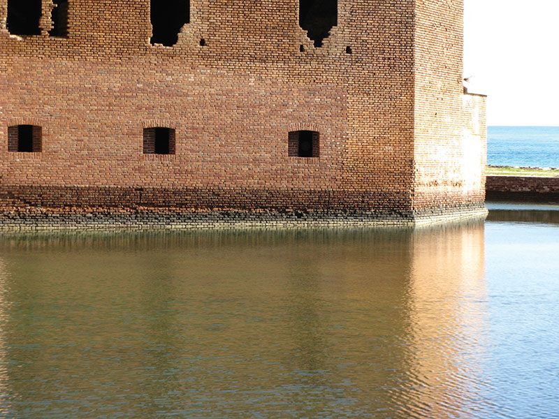
Figure 4: Settlements are as much as 24 inches per 200 feet. Here the water level in the moat makes settlement observation easy at Bastion 1.
Structural engineers are likewise accustomed, on many domestic buildings, to seeing masonry walls in need of repointing. But finding walls where bricks can be removed by hand is, fortunately, less common. Not here at Fort Jefferson, where 160 years of moisture migration through masonry has left mortar so deeply eroded that bricks falling and touching bricks below is far from uncommon (Figure 5).
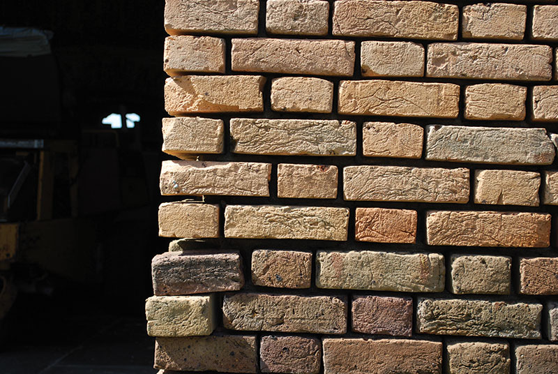
Figure 5: Mortar loss is severe in many areas.
Fort Jefferson’s greatest challenge comes from embedded iron (Figure 6). The great military engineer, Joseph Totten, designed iron shutters to close and protect the embrasure openings from cannon fire. Unfortunately, the eight-inch thick, 1500-pound armor blocks were embedded between 18 and 24 inches into the masonry walls of Fort Jefferson. On Fronts 4 and 6, as well as on other portions of the fort, the damage to the scarp walls has been so severe that the iron has had to be removed and the walls rebuilt to a depth of as much as 24 inches (Figure 7). Reconstruction of these vaulted, loadbearing masonry walls was particularly challenging, as was any work at all 70 miles from the nearest building supply store.
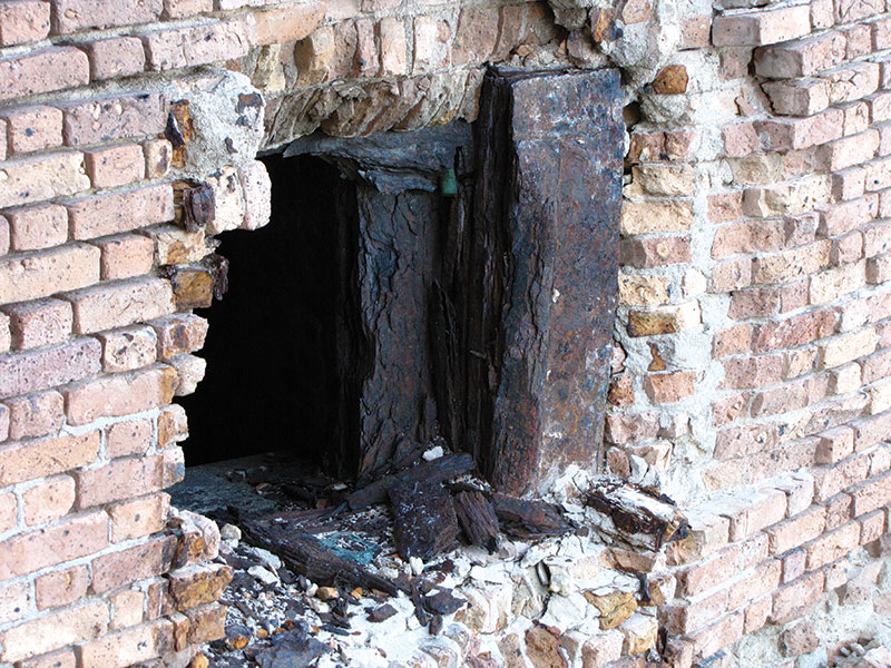
Figure 6: Corrosion of the embedded iron Totten shutters has severely damaged the masonry surrounding the embrasure openings.
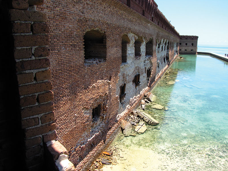
Figure 7: The damage to several fronts is severe but none as bad as that on Front 3.
The logistical challenges of working in a particularly isolated environment were handled by a construction crew under the direction of Ken Uracius of Stone and Lime Imports and owner’s representative Kelly Clark of the National Park Service. The engineering design team, with input from the architecture team led by Susan Turner of Lord Aeck Sargent, was able to focus on the challenges of large-scale brick growth, tying new vaulting into existing, horizontal reconstruction of a structure originally built vertically, and movement and potential collapse of unresisted thrust in the vaulting.
In modern construction, it is common to leave regularly spaced expansion joints in brick masonry, roughly every 24 feet in the southeastern Unites States. But the reconstruction of Fronts 4 and 6 required that roughly 400 feet of brick walls (Figure 8) be rebuilt without jointing and be done on a relatively tight schedule, with a non-hurricane working window of only six months a year. Fortunately, experience with similar issues at Fort Washington, Maryland had taught the team that they were able to force early permanent growth into the masonry with extended submersion of the bricks. Careful measurement work on extended brick soaks by Mike Schuller’s team at Atkinson-Noland of Boulder, Colorado had shown that seven to 28 day soaks could force enough growth in the bricks prior to their installation to avoid pushing the bastions apart. Without the pre-wetting, up to four inches of wall movement was anticipated.
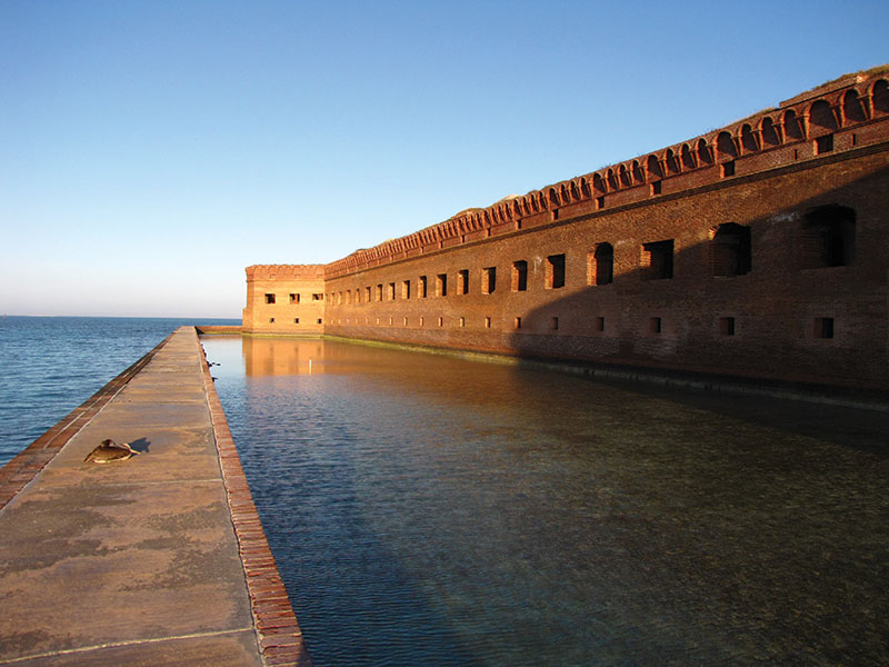
Figure 8: Front 4, now rebuilt, has over 400 feet of scarp without expansion joints.
Tying new vaulting on the face of the scarp walls back into the existing vaulting behind the scarp was interesting. The Florida State Historic Preservation Officer had asked the team not to use metals to make a tension tie of the new construction back to the existing, although Series 316 stainless steel and bronze both have reasonably good track records of holding up well in a marine environment. By judiciously cutting in the existing vaults and laying in tie bricks (Figure 9) then carefully laying out the brick coursing around the ties (Figure 10), the team was able to achieve a continuity similar to the original.
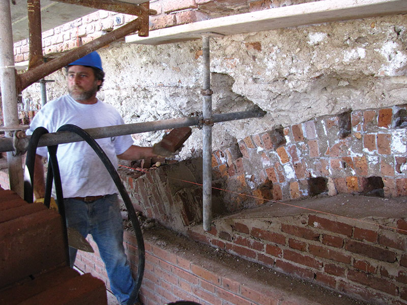
Figure 9: Tie bricks let into the undamaged vaulting tie the new vaulting into the old. The coral concrete is seen above.
Figure 10: Layout of the vaulting incorporated the tie bricks.
The original 19th century construction of the fort had, of course, proceeded vertically from the ground upward, building centering (formwork) for the vaulting and removing the centering once the vaults had been built. Reconstruction was instead horizontal (Figure 11), starting in the moat and moving horizontally into the scarp walls, shoring as necessary and depending on arching action overhead wherever possible. Reconstruction did require that the brick coursing be laid out, course by course and wythe by wythe, in order to match the tie bricks and achieve the final bond pattern.
Figure 11: Even though the original construction was built vertically from the ground up, the reconstruction had to be horizontal working from the interior outward to the scarp.
Finally, the greatest concern was the possibility that deep cuts in the scarp wall could destabilize the casemate vaulting behind the scarp. Three different analytical models (two finite element and one based on graphic statics) had shown that the arch supporting the vaulting was close enough to being unstable (Figures 12, 13 and 14) that the depth of the reconstruction had to be tightly limited and that certain columns had to be restrained during the disassembly and reconstruction.
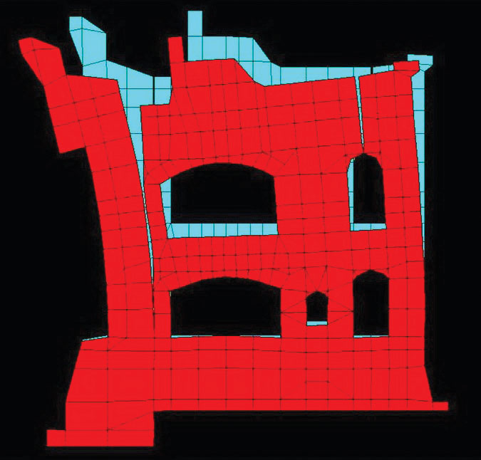
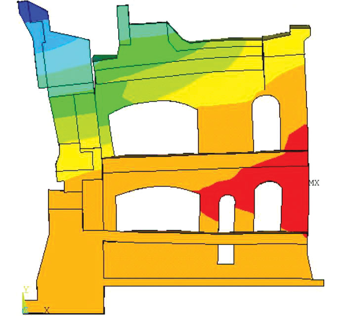
Figures 12, 13 and 14: Graphic statics calculations and two finite element models and confirmed that, without the scarp, the arch supporting the vaulting was on the edge of stability.
While only one of the four engineering challenges of the construction was readily apparent before the design started, a careful focus on the short and long-term behavior of the materials and of the historic structural systems, combined with input from the whole owner, design and construction teams led to a successful reconstruction of two of Fort Jefferson’s failing scarp walls.▪
This article is a condensation of presentations given at The Association for Preservation Technology, Victoria, British Columbia in September, 2011 and at The Masonry Society, San Antonio, Texas in October, 2011. Those presentations focused on different aspects of the same project.