
Stone Repair at the Fairmount Cemetery Mausoleum
Failing anchors in marble ceiling panels limit access for ceremonies and visiting patrons for interred loved ones in the mausoleum (Figure 1). Constructed in the 1920s, the Fairmont Memorial Mausoleum is located on the 150 acre grounds of the Fairmount Cemetery in Newark, New Jersey. The 250 foot long by 92 foot wide “H” configured building has an exterior built of granite upon a cast-in-place concrete frame and concrete floor infrastructure. There are four functional levels to the building, including the basement. The interior walls and ceiling are veneered with 1- and 2-inch thick marble stone panels. The interior mausoleum environment was not conditioned for climate, and over nine decades of changing weather has challenged both the stone durability and anchorage connections.

Figure 1. Exterior of the Fairmount Mausoleum.
Interior Stone Veneer Construction
The stone ceiling panels (Figure 2) are configured such that four (4) panels are butted to form a square. Each of the four panels has two edges common to another panel. They are suspended near center by copper wire ties attached to the stone edges by field-bending the wire to achieve about a 1-inch deep embedment in the stone. The wire’s opposing end is tied to the reinforcement bar of the floor above within a pocket created by chiseling the concrete cover to expose the ceiling rebar. The integrity and effectiveness of the existing ties are questionable, although such a system was not unusual at the time (Figure 3). Figure 4 illustrates the typical anchorage of the 8-gauge copper wire ties on a removed panel segment. Typically, the ties occurred at 12 to 16 inches from the unsupported free end, or mid-hallway location, of the panel. The outer perimeter of the 250 – 300 pound stone panels is supported by the vertical wall panels lining the hallway. The chase between ceiling panels and concrete differed by floor and the distance between the stone panel and concrete varied from 14 to 41 inches.
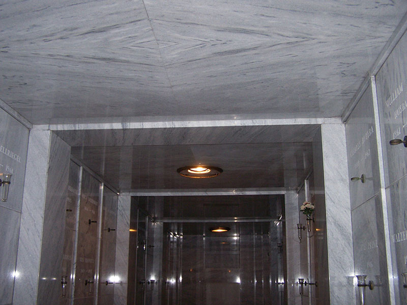
Figure 2. Interior of marble clad ceiling, beams, and walls.
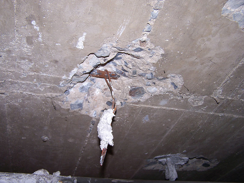
Figure 3. Corroded tie connection to steel.
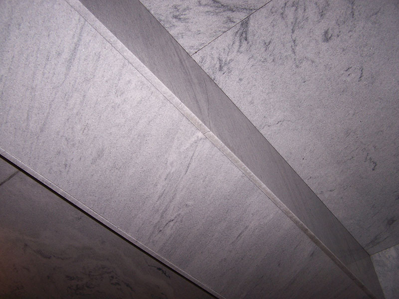
Figure 4. Typical 18- x 18-inch concrete beam enclosure in hallway.
The hallways throughout the building have marble encased concrete beams (Figure 4) occurring at approximately 8- to 10-foot intervals. Where concrete beams did not exist, a faux marble beam was provided for aesthetic continuity. The beams are covered on three sides with one inch thick marble. The marble pieces span the hallway and are simply supported at the end. A center wire tie was observed in an inspection of an exposed beam. The length of the beams varies from 7 feet to approximately 10 feet in some areas. At most locations, the marble box is a nominal 18 inches wide by 18 inches deep.
Ceiling Panel Re-Anchoring
The untimely collapse of a ceiling panel alerted the owners to the potential dangers of future collapse, and that repair was essential and urgent. The task to remove and reset the hundreds of heavy ceiling panels and three piece marble clad beams was not financially feasible. The marble veneer providing a wall covering was intact and functionally sound. Accordingly, the project team investigated a cost effective supplemental anchoring solution.
The challenges in developing the anchoring repair included:
- Developing a post-installation anchor to bridge chase distances of 14½ to 43 inches;
- The anchor must be capable of supporting a working load of 350 pounds tension and not induce tension loads on the existing marble panels;
- The anchor assembly must interact with the stone panels so that a face mount anchor will support the stone panel without stone fracture;
- Providing anchorage spacing and location dimensions that optimize anchor performance and does not over-stress marble;
- Developing an anchoring scenario for stairwell ceiling panels installed at an angle to match the pitch created by the stairs;
- Anchor finish must be aesthetically matched to the existing wall artifacts, sconces, gates and miscellaneous metal hardware;
- Developing a beam enclosure anchorage system to capture and support the marble box beam enclosures;
- Providing necessary installation means and methods criterion to assure marble and anchor combination effectively perform efficiently.
Anchors Developed
Marble Ceiling Panels
For the basic ceiling panel anchor, CTP developed a ½-inch diameter brass expander element, torque activated for the concrete connection. Torque provides an important means of inspection and performance assurance. The anchor’s embedment depth in the concrete was tested at a minimum of 1½ inches that averaged over 1200 pounds capacity and induced a preload of 1060 pounds. These results provided safety factors greater than the industry standard of 4:1. The 4-inch floor in which the anchor would be fastened allowed the air space to vary 2 inches shorter, providing a standard shaft length for the variable condition. The head of the anchor is a 1½-inch diameter stainless steel round bearing plate capable of supporting the stone. The two elements are connected by a suitably long stainless steel shaft assembly (Figure 5).
Figure 5. Details for ceiling anchors.
The marble ceiling panels were installed with corners butted at the center of the hallway. The 1½-inch diameter panel head would challenge the installation at this location due to the improbable ability to support each panel equivalently. As a result, a larger support area was required and a bearing plate was incorporated to support the panels in concert with the 1½-inch round panel head (Figure 6). Each bearing plate is manufactured of Type 304 stainless steel with a brushed finish. The bearing plate design was predicated upon the panels being supported at the outboard edge. As a result of this support configuration, the bearing plate will carry one half the weight of the panel. The ceiling panels are installed as pairs, meeting at center line of the aisle way ceiling. The bearing pad used was to cushion the contact area of the steel member against the stone.
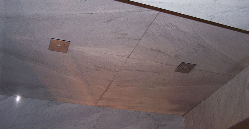
Figure 6. Typical ceiling support assembly.
Anchor assemblage components are manufactured of corrosion resistant materials. This style of anchorage was used throughout the project. The length of the anchors varied according to the cavity between the stone and the concrete slab, by floor. Three different anchor lengths were finalized after a field survey. Except for an extended drilling depth, all the assemblies followed the same installation instructions. This was an important feature in order to avoid customizing individual anchoring assemblies.
Stairwell Marble Ceiling Anchors
The assembly used in the stairwells for supporting the ceiling panels incorporates the same hardware as the ceiling panel support anchors. The panels in this area were installed to complement the stair rise and run angle. The panels are confined, and thrust loads due to the angularity were not an issue because of the panel confinement. A ceiling shim, manufactured of Type 303 stainless steel, was used to “normalize” the loading application from the plate to the Stone-Grip head.
Beam Enclosure Support Assembly
The beam enclosure support assembly incorporated the same style of anchorage to concrete used for other conditions. There are three (3) anchors per enclosure assembly and two encasements per beam (Figure 7). The anchor lengths vary with the depth of the beam.
Figure 7. Beam enclosure anchor.
The box-style beams’ varying height and width required an adjustable support hardware configuration. Basically, in order to transfer gravity loads, intimate contact with the marble is essential for the support characteristics of the load carrying system to be effective. Each box beam assembly consists of two upper-side mounted brackets. They carry the weight of the box beam and can be adjusted both horizontally and vertically. Additionally, they provide support to the ceiling panel adjacent to the beam. Each bracket can carry 240 pounds.
The top-side brackets are connected to a left- and right-side bearing bracket. This strap system envelops the beam and overlaps at the center of the beam bottom. Here too, the strap is capable of both vertical and horizontal adjustment to assure stone contact is made. Once the side brackets are positioned, they are bolted to the top-side brackets via a 3/8-inch stainless steel stud, nut and washer. The stud is factory welded to the side strap bracket. The intent is to support the beam in the event of a primary failure of the original tie/support system. Similar to the bearing plate detail, a “bearing pad” is used in the gravity bearing support areas. The top-side brackets and the left and right bearing brackets require bearing pads to insulate the stone from contact unit stresses.
To prevent the box beam side-wall stone panels from collapsing inward, they are anchored to the left and right strap assemblies as a final connection of the hardware to the stone. A masonry fastener incorporating Type 360 brass expander elements with 18-8 stainless steel hardware was applied. These fasteners are torque activated to maintain intimate contact of the marble side wall panels with the support hardware. The anchor length allows a portion of the expander to project from the rear side of the marble. As the anchor is torque activated, it creates a “rivet” connection effect between the stone and steel strap.
The bracket assemblies are manufactured of Type 304 stainless steel.
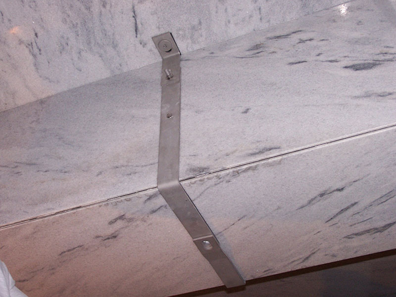
Figure 8. Box beam enclosure assembly for an 18- x 18-inch beam.
Summary
The finalized ceiling support assembly was used at 1,050 locations throughout the building for 1- and 2-inch thick marble. The marble beam enclosure and support assemblies were used at 370 locations throughout the building.
The entrance level (first floor) and second floor required the center anchor to span a maximum of 31½ inches, and the two top supports 14 inches; the third level was 43½ inches at the center support and 25 inches at the top side supports.
A critical element to the anchor installation was the method used to drill through the stone. Dry-drill carbide tip non-impact stone drilling bits were used for the task, as well as concrete drill bits 52 inches long having SDS drives to install the concrete anchors.
The quality and resourcefulness of the project team contributed to a successful execution of the restoration project, and provided a result that fulfilled functional and aesthetic concerns while completing the project weeks ahead of schedule.▪
Fairmount Cemetery Mausoleum Repair Project Team
Owner: Fairmount Cemetery, Newark NJ
Project Engineer: Structural Workshop, LLC, Parsippany, NJ
Project Architect: Cordasco & Socci Architects, Danville, NJ
Repair Contractor: Allied Contracting II Corp, Long Island, NY
Material Supplier: Construction Tie Products (CTP) Inc, Michigan City, IN
A similar article was previously published in the The Applicator, 1st Qtr, 2014, produced by the Sealant, Waterproofing & Restoration Institute. Content reprinted with permission.