
Taking the “Stress” out of Bridge Repairs
Route 8 over the little Hoosick River and B&M Railroad (a.k.a. The Hadley Overpass) in North Adams, MA has been undergoing a major rehabilitation. Ryan-Biggs Associates, P.C. is the structural engineering firm working as the construction engineer for the contractor, J.H. Maxymillian Inc. The approximately $30 million, multi-staged project involves replacement and repair of the various super- and substructures that make up the roughly 800-foot-long bridge, which spans over several parking lots, a river, and a railroad.
While much of the work was called out in the contract documents via the owner’s design consultant, a fair number of tasks (structural lifting, substructure shoring, active truss member replacements, etc.) were specified as delegated design to allow the contractor and construction engineer to develop the best means and methods. This article explains some of the means and methods designed by the construction engineer.
The bridge, owned by Massachusetts DOT, was constructed circa 1946 and consists of 15 substructures, 11 multi-girder spans, and one signature skewed through truss (Figure 1) spanning 160 feet. The project involved a triple-staged traffic pattern utilizing approximately two-thirds of the bridge width to continue carrying vehicles, while one-third was removed and replaced in stages until the full width of the bridge was replaced. For the multi-girder spans, the deck and existing girders were replaced. For the truss span, the deck was replaced while the superstructure was repaired and retrofitted.
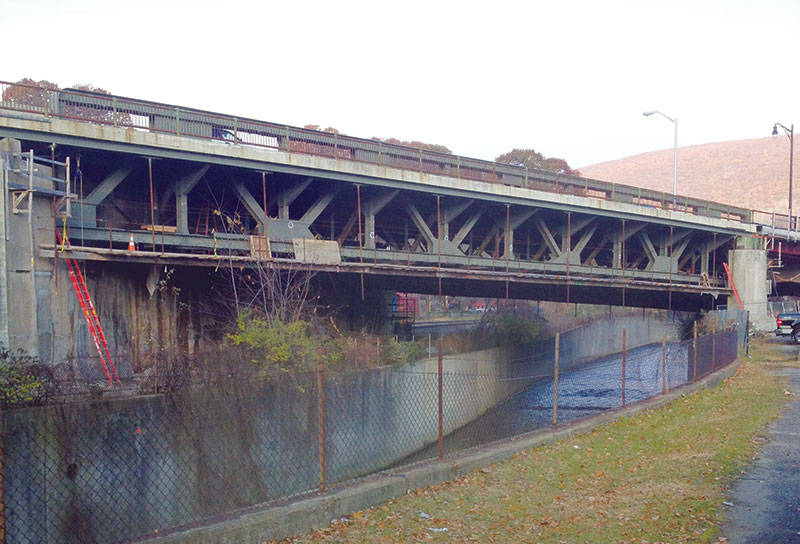
Figure 1. Skewed truss span elevation.
Conventional engineering was required for several facets of the project. The superstructures for spans 7, 8, and 9 were shored with steel moment frames founded on cast-in-place concrete footings (Figure 2). In addition, existing substructures were shored during concrete repairs using towers, and the construction engineer designed utility supports to span unbraced from pier to pier, designed temporary lateral-bracing systems to permit existing truss bottom lateral-bracing retrofits (Figure 3), and developed procedures for the systematic replacement of the existing truss end sway frames. The main trusses were also lifted and shored so that each bearing (520-kip design lifting load) could be removed and replaced.
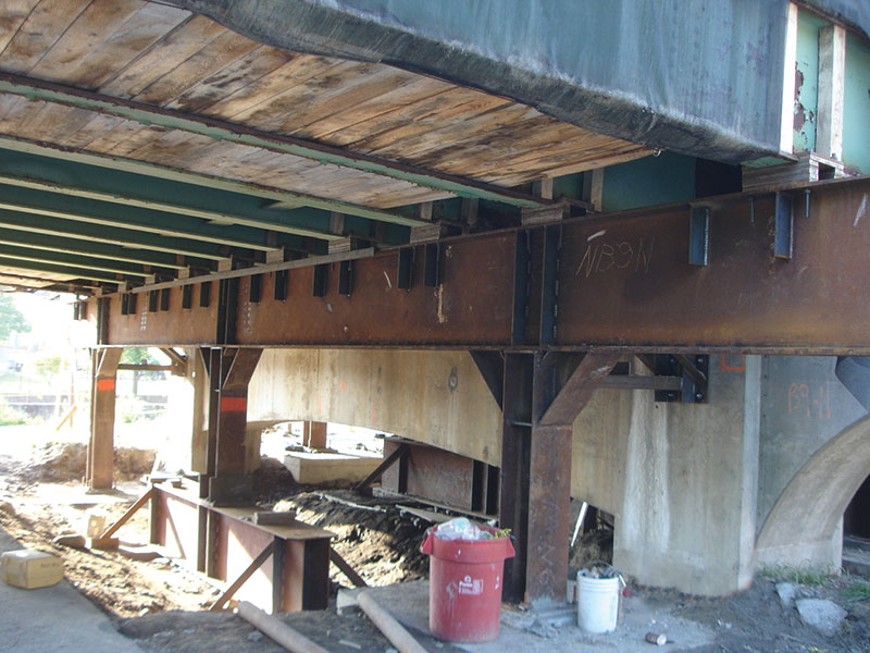
Figure 2. Span 9 shoring via steel moment frames.
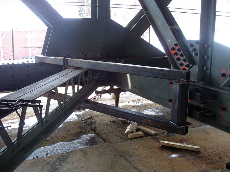
Figure 3. Bottom lateral retrofit shoring.
The project also involved some more “fun” (unconventional) engineering tasks with regards to the truss span; in particular, the main truss bottom chord detensioning. The main trusses span 160 feet between bearings and are spaced 45 feet apart, carrying three lanes of traffic, two outboard sidewalks, and a bank of utilities. The two main trusses are interconnected with floor trusses spaced 16 feet on center at each main truss panel point. The main trusses are heavily skewed such that one end of a floor truss is supported at mid-span of one main truss, while the other is at the bearing of the other one (Figure 4). The floor trusses span 45 feet between main trusses – or 36 feet, 27 feet, 18 feet, and 9 feet where they span from main truss to the bridge seat at the skewed portions of the superstructure – and are approximately 9 feet 6 inches deep.
Figure 4. Schematic truss span plan.
Analysis was complicated given the large skew of the bridge, as well as the number of load cases and combinations. The construction engineer used RISA-3D software to envelope the forces given the staged deck strips (on or off), temporary concrete barrier locations, live load (far side and/or near side), sidewalk (on or off), under-bridge suspended platform (on or off), wind load (on or off, to the east or to the west), etc.
Needless to say, the main truss bottom chord is not a single 160-foot long piece from bearing to bearing, but rather is made up of five 32-foot pieces with four splices. The splice plates had experienced a fair amount of deterioration over the years and were noted by the design consultant to be replaced. With nearly 1,000 kips of tension going through the bottom chord at mid-span, it was not just a matter of taking out the splice plates and replacing them. Engineering and construction issues to be addressed included:
a) What would hold the truss together without the splice plates?
b) What would the force distribution be in the chord after the project if the plates for a given splice were replaced one at a time?
The solution was to detension the bottom chord (i.e., bring it to a state of near zero stress) so that the splice plates at a particular panel point could be replaced simultaneously and, once retensioned, share the load equally. Since the panel points in question contained a main truss diagonal, the average chord force was used as the detensioning force. One side of the joint would still have a residual amount of tension, while the other side would have a small amount of induced compression. This was deemed acceptable by the owner and design consultant since all were in agreement that attempting to resolve the main truss diagonal forces to get the bottom chord force to true zero would have been even trickier.
The goal of the temporary detensioning component design was to develop a system that could be reused at multiple locations, but was still efficient considering that the bottom chord forces varied from around 600 kips to about 1,000 kips. This was accomplished by designing a single setup for about 340 kips and using multiple setups for the incrementally higher loaded areas of the bottom chord. At the highly loaded panel points, three setups were used (1,020 kips total capacity) on each side, while at the lighter loaded panels points, only two setups were used (680 kips total capacity). The multi-setup system also proved advantageous for connecting the vertical load transfer plates to the existing main truss bottom chord. The smaller the vertical transfer plates, the easier it was to find symmetric locations on either side of the panel point to install the vertical transfer plate while avoiding the existing bottom chord top and bottom stay plates. In addition, the owner wanted as few new holes in the existing bottom chord as practical for the connection of these temporary components to the existing bottom chord; therefore, existing rivets were removed and replaced with high-strength bolts. All of the existing rivet spacings were field-measured so that the bulk of the components could be shop-fabricated. The vertical transfer plates served as thrust points against which the hydraulic rams could ultimately pull (Figures 5 and 6).
Figure 5. Vertical transfer plate as detailed.
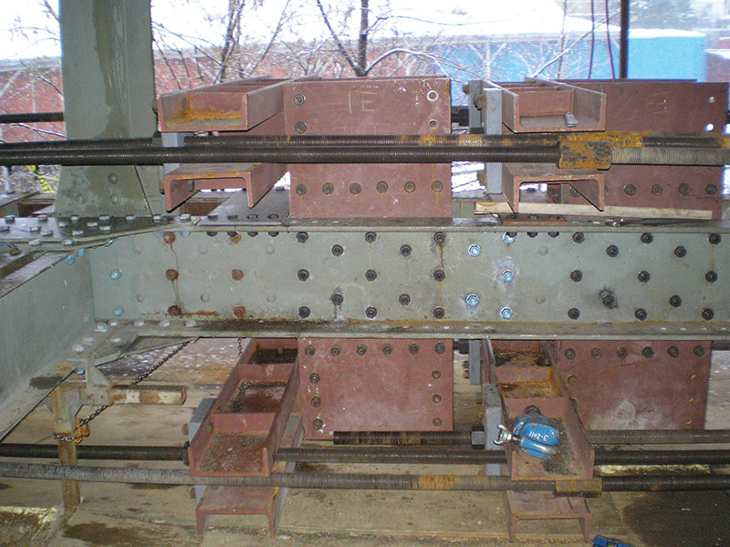
Figure 6. Vertical transfer plate as constructed.
Upper and lower horizontal transfer channels were installed at each vertical transfer plate, which projected both above and below the bottom chord. The horizontal transfer channels projected both to the inboard and outboard of the existing main truss bottom chord. This would keep the threaded tie rods out away from the panel point, giving the contractor room to remove and replace the splice plates. In addition, the horizontal transfer channels at the first, second, and third setups projected progressively longer so that the threaded tie rods could pass by those from the preceding setup. Ultimately, each transfer channel was connected to its sister on the opposite side of the panel point with 2-inch-diameter, 150-ksi threaded rod (Figures 7 and 8).
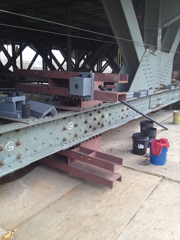
Figure 7. Transfer plates and channels.
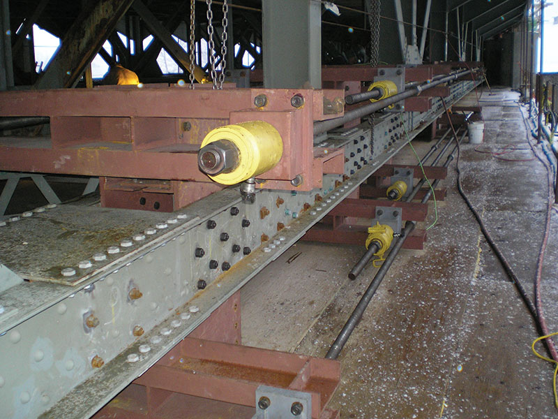
Figure 8. Hydraulic rams and threaded rods.
There were four threaded rods per setup: upper outboard, upper inboard, lower outboard, and lower inboard. Four 60-ton hollow-cylinder rams “stretched” each of the threaded rods to specific pressures depending on the panel point being worked. Hydraulic manifolds ensured uniform pressure distribution. Tensioning of the rods compressed the bottom chord, thus counteracting the existing axial tension force, and in turn bringing the existing main truss bottom chord to a near zero state of stress at the panel point (see Figures 9 and 10 for before and after ram pressurization).
Figure 9. Truss elevation before ram pressurization; red fully tensioned, blue near zero.
Figure 10. Truss elevation after ram pressurization; red fully tensioned, blue near zero.
Before, during, and after hydraulic pressure application, various points were benchmarked and monitored for both horizontal and vertical movement using high-tech lasers and, as a low-tech (yet highly effective) back-up, stretched thin piano wire. The existing trusses appeared to be stiffer than the 3D computer model suggested, with all movements and measurements at the lower ends of the anticipated ranges. For best monitoring practices, hydraulic pressure application occurred at about 4:00 am, with the bridge temporarily closed to traffic so that moving live loads would not affect the load transfer or the anticipated measurements.
After hydraulic pressurization, the rams were mechanically locked off and the contractor could remove and replace all of the splice plates at the panel being worked. Each panel point required about 10,000 pounds of temporary steel to replace about 200 pounds of permanent splice plates. After retensioning the system, the owner had confidence that the splice plates had equal known amounts of stress, which made future analysis of the truss less “stressful.”
There are a few more phases of work remaining, but the project is expected to be completed in 2014. With direct communication and a collaborative effort among all team members, the Hadley Overpass project has “overpassed” the expectations of those involved in this interesting bridge rehabilitation.▪
Project Team
Construction Engineer: Ryan-Biggs Associates, P.C., Clifton Park, NY
Contractor: J.H. Maxymillian Inc., Pittsfield, MA
Owner: Massachusetts Department of Transportation
Design Consultant: The Louis Berger Group