
At eight stories high and comprised of reinforced concrete flat plate construction (concrete slab without beams), the residential building at 653 Tenth Avenue in New York City boasts distinct features that make this building more than the average ‘flat plate’. These include a column free corner with cantilevers of up to 20 feet long and a large amount of exposed reinforced concrete structure, both of which were achieved with a structural slab of no more than 8 inches thick on the interior of the space.
Column Free Corners
Maintaining prime views and ample daylight was extremely important to the architectural design of this building. No less important was maintaining the desired visual impact of the façade, namely, a non-uniform window pattern. Herein lay a conflict for the buildings designers. Maintaining the desired parameters for light and site lines would not permit the introduction of a corner column to the space at the south-east and the south-west corners of the building. Even an architecturally exposed round column or small column would have had drastic impacts on the site lines. Making matters worse, the typical corner window arrangement utilized in this building consists of an L-shaped window, with the long leg of the L measuring approximately fifteen to twenty feet and the shorter leg measuring approximately seven feet. Moreover, the non-uniform window pattern of the façade required that the orientation of the longer window be on alternating sides from floor to floor. As such, the introduction of a column anywhere within twenty feet of the corner in the east-west direction or fifteen feet of the corner in the north-south direction would compromise these views (Figures 1 and 2).
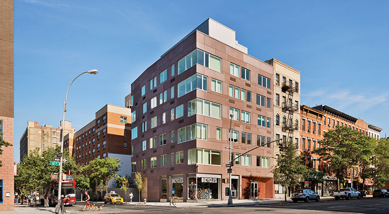
Figure 1. Overall view of the building – South East corner. Courtesy of Eduard Hueber/archphoto.
Figure 2. Rendering showing the structural frame of the vierendeel truss. Courtesy of Cannon Design.
Numerous solutions were investigated to avoid the introduction of the corner column. Deep cantilevered beams upset into the exterior wall were considered, but the locations of the HVAC units in the exterior restricted the depth of the cantilevers to sixteen inches – far too shallow of a beam to cantilever up to twenty feet. The use of a much thicker slab without beams was considered as well. However, the impact on the floor to ceiling heights would have negatively impacted the usage of the space. Even if either of these options had been architecturally feasible, trying to maintain the deflection requirements (considering instantaneous deflection along with long term deflections) would have been extremely difficult.
After much review and discussion, the introduction of a Vierendeel truss frame within the exterior envelope was suggested for its consistency with the irregularity of the façade and its windows, as well as cost effectiveness in supporting the long cantilever. A Vierendeel truss is a frame that utilizes the bending of vertical members and the horizontal chord members with rigid connections. This is in contrast to a standard truss which relies on axial forces in diagonal members to transfer loads. While a typical truss has minimum bending in its elements, the Vierendeel truss has significant bending. Although this results in a relatively low stiffness, it still remains far stiffer than a simple cantilever without this frame action.
A shallow eighteen inch deep beam by sixteen inches wide was introduced around the perimeter. The portion of the span (approximately eight and a half feet) nearest the corner was achieved with a simple cantilever, while the portion of the span (up to about thirteen feet) closest to the column utilized the Vierendeel. The Vierendeel panel had an effective depth of approximately ten feet (the story height), making it extremely stiff and keeping the deflection at the tip to a minimum. In addition, the Vierendeel truss cantilevered in two directions, interlocking at the corner (Figure 3). This results in the entire corner of the building moving together from floor to floor, thereby reducing the differential deflections. Since the floors are all locked together in one system, deflections for live load could be considered utilizing a reduced live load since the system supports a far larger tributary area than just one floor.
Figure 3. Unfolded elevation of the Vierendeel truss.
While using Vierendeel trusses is relatively common, using them in this manner is far more unusual. As such, basic modeling of the system was necessary to verify its feasibility. After initial modeling, it was clear that the use of the Vierendeel truss was feasible and would result in relatively small deflections at the corners. Controlling the deflections in the corner was important not only for the comfort of residents, but also for the initial erection of the façade. Special attention was paid to the concern of long term deflection (primarily creep) by way of additional compression steel added to the frame elements in bending. The Vierendeel frame was reliant on several floors working together. The design of these corners required additional inquiry into the staging and construction sequences of the building. This necessitated specific instructions related to shoring these members, so that the shoring designed by the contractor properly met the design concept. To ensure proper fit up of the façade, minor cambering of the corner of the frame was placed such that the façade installation could start with a frame that began as straight as possible.
The construction of a concrete Vierendeel truss was no more difficult than standard concrete construction. The beams/chords and verticals are formed the same as conventional beams or columns. While the construction details of these elements needed to be more descript in several areas (such as development lengths, tie locations, clear covers, joint confinement, etc.), it resulted in minimal extra work for the contractor (Figure 4). This resulted in little additional cost due to the introduction of the frame.
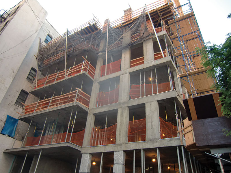
Figure 4. The Vierendeel truss under construction. Courtesy of Jesse Cooper, Severud Associates.
Gaining Key Space with Architecturally Exposed Concrete
It was imperative that the building footprint be kept as small as possible. Any additional space required for the building footprint would have taken away from key amenities, such as the relaxation garden at the west end of the site (Figure 5). The architect desired the unrefined look of exposed concrete to help create the calming effects of the exterior space. Exterior walls of exposed concrete cast over ship lapped old lumber were used to create visually pleasing elements. To tie the visual into the interior spaces, an exposed concrete finish was selected for the central core areas of the floors. In addition to achieving the specified look, this helped reduce the overall thickness of the walls, thereby optimizing the space. After many meetings, discussions, and trials, a rough finished exposed concrete was selected. By utilizing a rough finish, many of the more costly requirements typically associated with architecturally exposed concrete were eliminated (special forms, ties, etc). This brought the cost of the exposed walls well below that of typical architecturally exposed concrete while still maintaining the desired architectural intent.
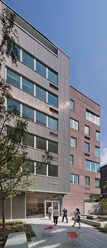
Figure 5. Exterior view of the relaxation garden with the building and the architecturally exposed concrete wall in the background. Courtesy of Eduard Hueber/archphoto.
Where exposed concrete was desired for the exposed underside of the floor slab, similar economy was desired. By simply adjusting the concrete mix with admixtures to make the concrete more flowable, the floor slabs could be cast with standard formwork, but create a rough architecturally exposed concrete with little additional cost.
Conclusion
As engineers, we approach every building with new ideas and a fresh outlook. Even buildings which may appear to be ‘cookie-cutter’ on first glance can pose situations which necessitate creative solutions. The best solutions are often those that reapply commonly used principles in innovative ways. In the case of the residential building at 653 Tenth Avenue, the solutions described herein allowed the architects to maximally achieve their visual intent while providing an economic and functional design solution.▪
Project Team
Structural Engineer: Severud Associates Consulting Engineers
Owners: WAF Munich
Architects and MEP Engineers: Cannon Design
Owner’s Representative: Levien and Company
Site/Civil/Geotech: Langan Engineering
General Contractor: Dynatec Contracting, Inc.
The author would like to note the contributions of Jesse Cooper, Gustavo Amaris and Cawsie Jijina, P.E., SECB, to this article.