
Pennoni’s involvement with the adaptive reuse of an existing historic building included the development of several innovative structural solutions. Part 1 of this article (February 2014) provided a history of the building and the initial major renovation challenges (Figure 1). This article will discuss life safety improvements and enhancements to utilization of the 12th floor and roof spaces.
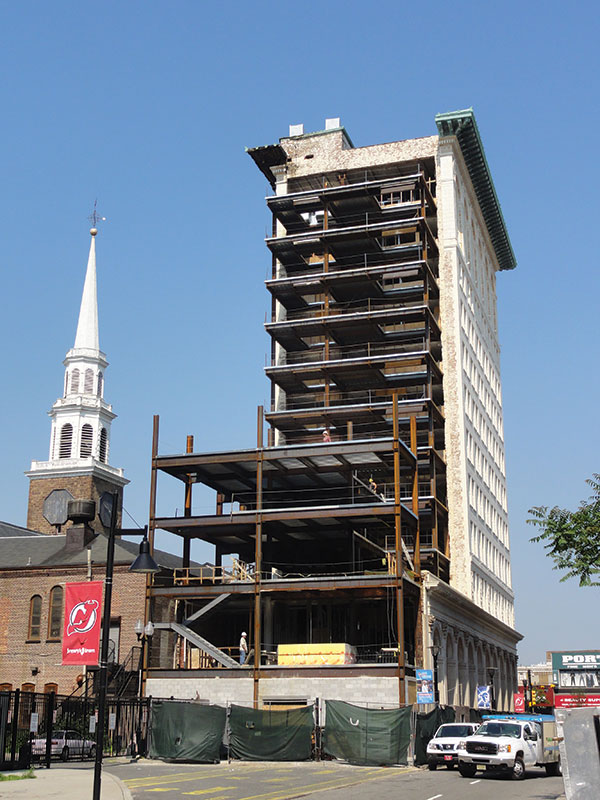
Figure 1: Partially erected stair and addition framing.
Improvements in life safety codes since the original construction of this mid-rise building meant that the existing egress paths through the structure were no longer adequate to support the use of the structure as a hotel. In order to rectify this, the project added 800 square feet of floor space to each floor, containing a new stair and elevator. Accessing this new 9-story tower required demolishing a large portion of the existing east exterior wall. Supporting it presented significant structural challenges, because the footprint of the addition was located directly above the existing low-rise building but did not match its column grid. Pennoni presented two alternatives. The first consisted of vertical diagonal braces supporting the floor beams of the addition from the existing east exterior columns, such that each level of the new tower was essentially “corbeled” from the mid-rise tower. The second option consisted of new columns at the east face of the addition that would be supported by significantly reinforcing the existing beams of the existing low-rise roof to act as transfer girders. Ultimately, the design team chose the latter due to architectural restrictions in the geometry and location of the diagonal braces proposed by the first option.
After establishing the support scheme for the stair and elevator addition, Pennoni concentrated on evaluating the impact of the new addition on the existing structure. First, the double spandrel beams were analyzed for the loads imposed by the reaction of the new adjacent framing. Because the outer beam was primarily designed to support only the east exterior brick cladding that was being removed to allow for the addition, it was able to support the new beams of the stair tower without the need for reinforcement (Figure 2). Furthermore, the new net reaction at the columns supporting the outer beam of the double spandrel was approximately the same as the original condition. Transferring the lateral load of the stair tower addition into the lateral-load-resisting system of the existing mid-rise structure involved drilling horizontal epoxy dowels into the existing concrete slab at each level. Additionally, placing continuous reinforcing steel at the north and south ends of the addition, and doweling it into the adjacent existing concrete slab, created diaphragm chord members in the new slab.
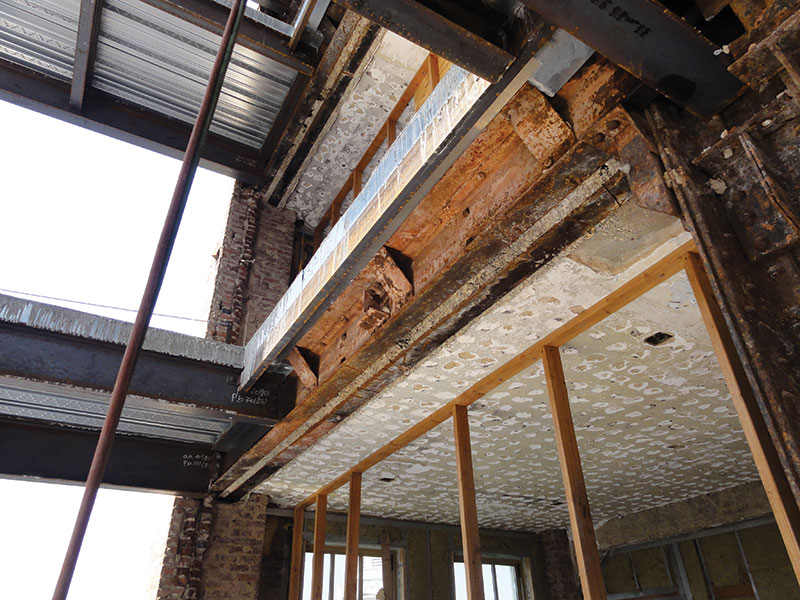
Figure 2: New tie-in conditions at existing spandrels.
It was also necessary to investigate the distribution of new lateral forces created by expanding the sail area and square footage of the structure as a result of the additions. The lateral load resisting system of the existing structure had sufficient capacity to support these loads based on the exception allowed by the International Existing Building Code (IEBC) when the increase is no more than 10% over the original. The lateral resisting system used in the First National State Bank Building involved angle bracket kicker braces, encased in concrete, that attached the girders and columns together to form rigid moment frame connections at a number of locations throughout the building. This type of system was first used in the Reliance Building in Chicago in the mid-1890s.
The final structural engineering task for the stair and elevator addition involved reinforcing the existing third floor beams of the low-rise that were to support the new columns above by adding transverse stiffeners beneath the new column flanges. These stiffeners also transferred the new concentrated column base reactions to new transfer girders built tight to the bottom flange of the existing beams. The transfer girders are designed to support the entire column reaction, which allows the existing beam to transfer the load through the stiffeners to the new beams below and still function as a part of the existing third floor framing. The top flange of the transfer girder was welded to the bottom flange of the existing beam to enable the transfer of any horizontal shear flow between the two members. The increased reactions where the transfer girders connect to the existing columns required stiffened seat connections to strengthen the existing conditions (Figure 3). Welding HSS sections to the column flanges increased the weak-axis bending capacity of the column section to handle the resulting eccentricity.
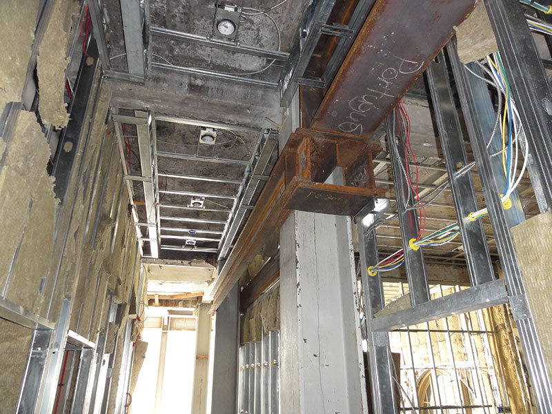
Figure 3: New transfer girder connection at existing column.
Transforming the existing roof of the mid-rise building into an occupied terrace with outdoor dining required reinforcing the structure to support the new loads. While the existing drawings showed the steel framing, they provided no concrete slab information such as compressive strength or thickness. They also showed no roof sections, and it was suspected that the slope that existed for proper drainage involved a concrete topping slab in addition to the main roof slab. Roof cores at suspected high and low points enabled determination of the slab composition and physical properties, confirming Pennoni’s suspicions. This meant that it would be possible to use the existing slab in conjunction with new steel channel shear connectors on top of the existing beams to create composite action with the primary roof girders, thereby increasing their structural capacity.
The existing roof beams spanning between girders would be overstressed as a result of the heavier loading associated with the new terrace. In order to prevent this, new steel roof beams were added between the existing ones in order to decrease the tributary width (Figure 4). The higher yield strength of the existing steel was taken into consideration, determined via coupon tests, as opposed to the strength provided by historical databases. An alternate method to reinforce the roof structure was to weld steel split T or WT sections to the underside of the existing beams and girders. However, this method was not used because of the excessive demolition that would have been required in order to remove a portion of the concrete encasement that provided fire protection for the existing beams.
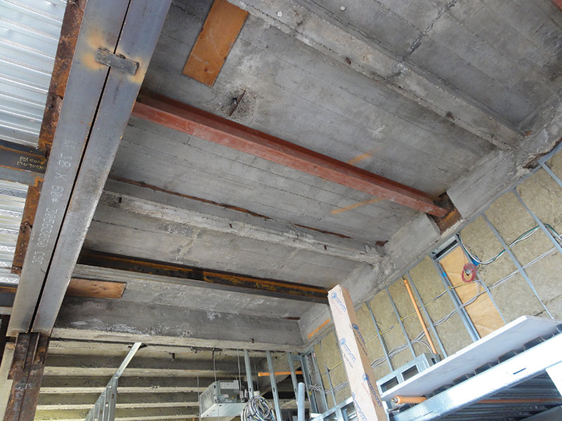
Figure 4: Existing beam and slab strengthening.
Completing the renovation design required solving several other challenges, which included green initiatives to conserve energy via the introduction of a solar panel array along the top of the existing roof’s copper cornice. The outrigger support structure did not have sufficient capacity; therefore, a new structural frame was designed to cantilever over and above the existing cornice roof, by connecting to the exterior column extensions located within the existing parapet. In addition, two new energy recovery units (ERUs) were required in order to provide conditioned air efficiently throughout the structure. However, the large size and weight of the ERUs made it difficult to find acceptable locations for their placement. The higher existing floor-to-roof height at the 12th floor made this location an attractive option. In order to limit the resulting loss of floor space, the units were stacked by providing a new steel dunnage frame supported by the existing floor girders at the lower ERU, and a new steel frame that spanned between the existing steel columns at the upper ERU (Figure 5). Taking advantage of the increase in steel yield strength found via coupon tests eliminated the need for reinforcing. The height at the 12th floor also allowed for the construction of luxury suites with lofts constructed of metal floor decks and cold-formed steel walls bearing on the existing floor beams, which were reinforced with new steel split T sections welded to the underside in certain locations where the existing structure was overstressed.
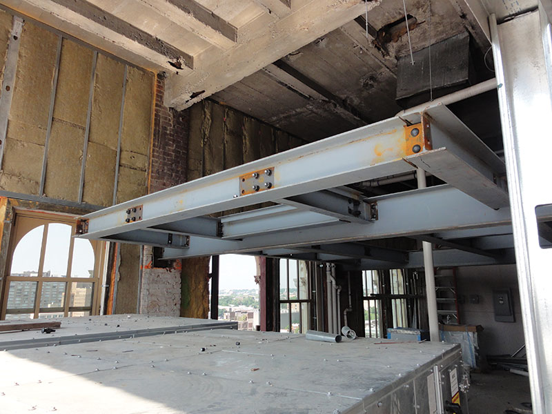
Figure 5: New 12th floor interior dunnage frame.
Upgrading the vertical transportation systems with machine-room-less custom elevator cabs to fit the existing floor openings also posed challenges that included supporting the elevator sheave beams and providing the required overhead clearance. Ultimately, this resulted in the need to demolish a portion of the existing elevator penthouse roof structure and design a new one that met the needs of the new elevator manufacturer. The existing roof beams supporting the new penthouse also required strengthening. Upgrading the original four-story stair and elevator tower located at the rear of the facility involved the complete demolition of the masonry walls and steel framing from the ground floor up, with a new six-story tower taking its place.
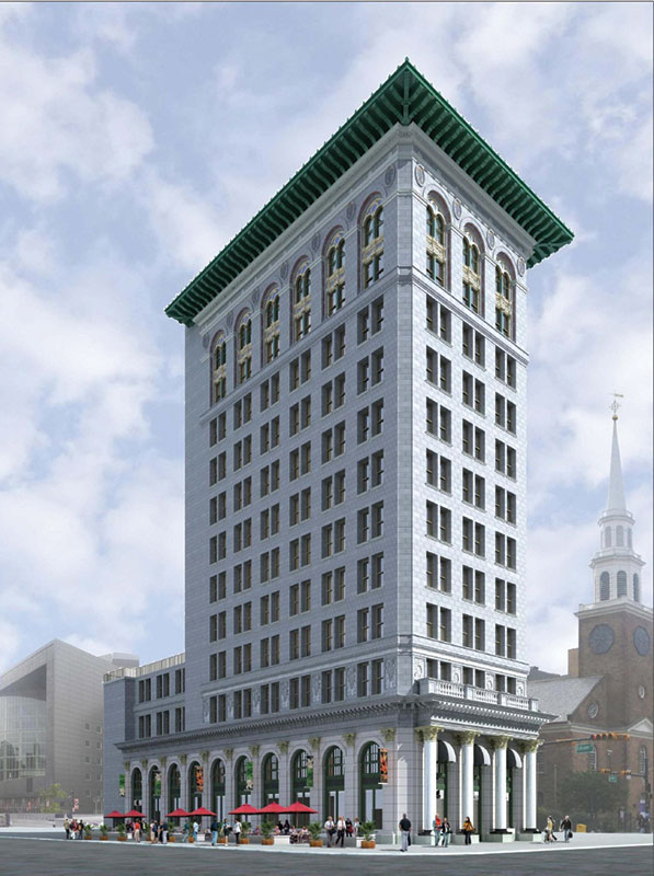
Figure 6: Rendering. Courtesy of DeRosa Group Architects.
A 2012 report entitled, The Greenest Building: Quantifying the Environmental Value of Building Reuse, produced by the Preservation Green Lab of the National Trust for Historic Preservation, found that when comparing buildings of similar size and function, environmental savings are almost always found through building reuse, rather than demolition and new construction. Additionally, the article found that reusing existing buildings provides benefits to the surrounding community and local economy. The adaptive reuse of the First National State Bank Building is an exemplary rehabilitation project highlighting these social, economic, and environmental benefits by restoring pride in a historic structure and creating revitalized business in an evolving neighborhood, all while decreasing the overall carbon footprint (Figure 6). This transformation would not have been possible without creative, yet simple and constructible, structural engineering solutions for the complex renovation changes.▪