
Steel fabricators have been using three dimensional models to detail structural steel for many years now. In many modern shops, all information required for the fabrication of a project is included in the detailed model, including dimensional information, material grades, piece marks and specification of welds. Much of the CNC equipment used in the fabrication is programmed directly, using digital data derived directly from the models using a combination of commercial and custom software that is tailored to the particular equipment and practices used by the fabricator. Modern beam line equipment even etches the locations of connecting pieces, part marks, weld symbols, faying surfaces and shear tab connections to guide the manual assembly processes that follow.
With automation at such a level today, the traditional two dimensional shop drawing is used for fewer purposes than before. In the state of the art shop, the two dimensional drawings are primarily used as a reference document for piece assembly by shop labor and inspection. Yet, in most cases, the two dimensional drawings remain the primary means for the engineer of record to review the steel fabrication information for conformance with the design intent. This requires the inclusion of far more information than is required for their use in the shop. Further, incorporating comments made in the structural engineer’s review requires modification to both the three dimensional model and two dimensional drawings. Even with modern detailing software automating the generation of two dimensional piece drawings from the fabrication model, approximately one-third of all detailing hours are spent creating and editing the two dimensional drawings (Figure 1).
Figure 1: Typical timeline for development of detailing model and shop drawings.
The Herrick Corporation, with the help of one of its subcontracted detailers, has recently developed a process to enable the structural engineer of record to review, comment on and approve the fabrication model directly without the need for any two dimensional drawings. This process, dubbed “3D In-Model Review”, is enabled by a proprietary application created using the Tekla Open Application Programing Interface (API) and operates in conjunction with the Tekla Structures software platform.
For Herrick, having the structural engineer of record review within the model allows the production of shop drawings to occur all at once, following the approval of the model by the structural engineer. This economizes detailing hours for drawing production and streamlines the incorporation of review comments into the final detailing model. The time required to prepare packages for the structural engineer’s review is also minimized, since shop drawing production does not occur prior to the submittal. This can benefit the project by allowing additional time to complete design for a fast track construction schedule, or by allowing an earlier construction start for an established design.
The 3D In-Model Review application was designed to maximize the use of the three dimensional model and mimic the processes involved in a traditional paper shop drawing review that engineering firms have grown accustomed to. Models are submitted as Tekla Structures files through a file sharing site or FTP server, and remain with the design team as a record document. The models are broken down in manageable segments comparable to traditional shop drawing packages, typically broken into erection tiers and sections. The extent of a typical submittal is shown in Figure 2.
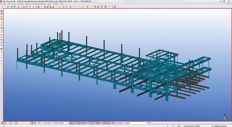
Figure 2: Typical size of a 3D In-Model Review submittal for SEOR review.
Upon opening the model, the structural engineer is presented a default filtered three dimensional view of the specific steel members that are to be reviewed in the submittal. All members in the submittal package are color coded, representating current submitted status prior to any design team review status. Members colored cyan have no open issues, and members colored orange have a comment from the fabricator to the SEOR, for example. The reviewing engineer can systematically interrogate the pieces of interest for the review using the 3D In-Model Review application, which provides a summary information dialogue for data relevant to the review, such as member type, profile and material grade.
After selecting an individual main member and viewing the basic information through the approval dialogue window, Tekla Structures automatically generates additional views with detailed information on the connections such as the quantity, size, spacing and type of bolts, size and type of welds, and connection plate grades and dimensions (Figure 3).
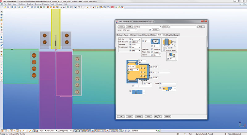
Figure 3: Display of connection detail in 3D In-Model Review application.
The main approval dialogue window (Figures 4 and 5) provides the engineer numerous fields to comment in, including the ability to attach commented screenshots, design drawings, sketches, etc. After the engineer has reviewed the member and determined the approval status, the comments are permanently recorded in the model for transmittal back to the detailers. The visual representation of the member changes in the Tekla interface to one of the following: green for “Approved”, yellow for “Approved as Noted” or red for “Revise and Resubmit”. This visual cue is used by the reviewing engineer to track progress and to rapidly convey the approval status of the members within the model.
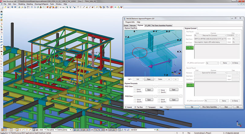
Figure 4: Three dimensional view of model with 3D In-Model Review main approval dialog.
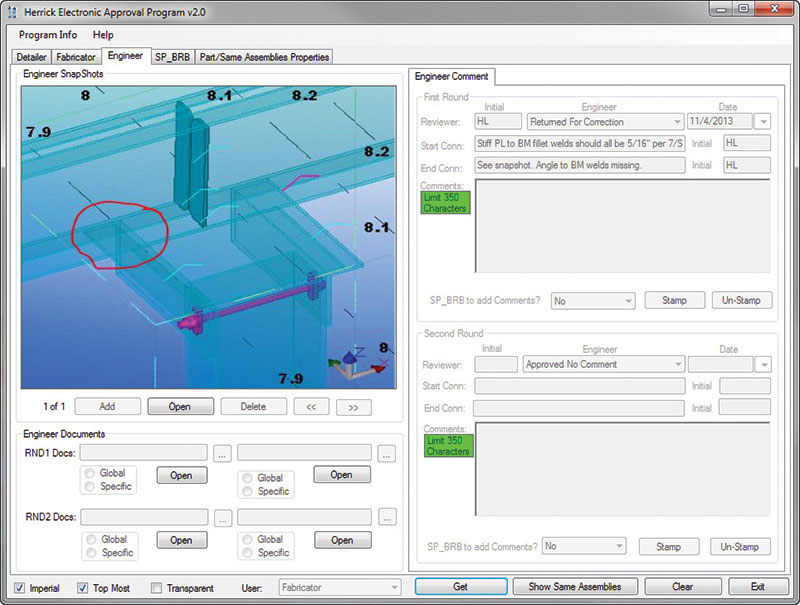
Figure 5: Enlarged view of the 3D In-Model Review main approval dialog with image attachment illustrating the review comments.
KPFF Consulting Engineers is currently partnered with Herrick as part of an integrated project team on a new 560,000 GSF hospital facility in Southern California, which utilized the 3D In-Model Review process. A review team of four engineers collaborated on reviewing the fabrication models for conformance with the structural design drawings.
Work was split between the review team with multiple reviewers working in parallel on each package. Each reviewer was assigned a family of elements (e.g. beams, columns, etc.) and worked geographically through the individual members in the model using the color key to track progress. All information needed for review was quickly available to the reviewer through dialog boxes and views generated automatically through Tekla Structures. All miscellaneous pieces, such as connection plates and stiffeners, are associated with the members they attach to, so all pieces are reviewed through viewing the main members.
After the initial training and learning curve on the use of the 3D In-Model Review Application, the review team found productivity to increase on each subsequent submittal. The reviewers found that the first review of an individual member was typically slower than in a two dimensional drawing review due to the multiple dialogs and views required to encompass all of the pertinent information. After reviewing one instance of a connection detail or common member, however, all other instances could be immediately identified and approved or commented on in one action. This led to an increase in productivity as the review progressed. Though the review of the models is ongoing at the time of publication, KPFF projects that review hours per ton of steel will be lower using the 3D In-Model Review process when compared to the review of two dimensional drawings or three dimensional models with embedded two dimensional piece drawings.
A final, immeasurable benefit for the review team is the dynamic nature of the three dimensional visualization of the project. There is an immediate familiarity with the three dimensional image of the work under review, which allows the review team to see each element in the context of the surrounding members and in complete detail before the design is sent off to fabrication. The interface also removes some of the drudgery associated with paging through huge stacks of paper drawings. The three dimensional visualization of the model was also useful for communication between team members, as screen captures could easily be annotated with questions or comments and emailed or included in the comments as file attachments.
Though still in its infancy, 3D In-Model Review is proving to be a promising tool with productivity benefits for both fabricator and designer. As the tools continue to improve, they are likely to become more widely used to deliver steel building projects ever faster.▪