
Seismic design of buildings using repetitively framed CFS (CFS) members has largely been enabled through a series of dedicated tests conducted on shear walls and compiled for convenient use in the AISI-S213 standard, supported through the seismic response modification coefficients and procedures in ASCE 7. This approach has served engineers and industry well, but has not provided a clear path towards the development of new and novel seismic force resisting systems utilizing CFS, nor does it provide the necessary knowledge for modeling CFS buildings as systems. At its core, the seismic performance-based design (PBD) paradigm presumes an ability to efficiently model the key nonlinearities and redistributions inherent in a building under seismic demands. For CFS structures, important knowledge that is required to create such models for PBD is missing. To varying degrees, fundamental gaps exist with respect to the hysteretic performance of CFS connections, members, assemblages, and full buildings. Characterization and implementation into models are also lacking. The CFS-NEES effort has as its aim the development of experimental benchmarks, fundamental characterization, and the demonstration of efficient means to model CFS structures – even with their inherent complexity.
Building Archetype
Central to the CFS-NEES effort was the professional design of a two-story CFS commercial building sited in Orange County, CA (site class D) that is 49.75 feet x 23 feet in plan and 19.25 feet tall, with a total seismic weight of 78 kips. The design was completed by Devco Engineering, with input from the project team and the Industrial Advisory Board. A design narrative, complete calculations, and full drawings are available.
A key feature was the selection of ledger framing, a choice that was strongly advocated by the Industrial Advisory Board based on current practice. In ledger framing, the building is constructed one floor at a time, but the floor joists are hung from the top of the studs. The joists and studs are not aligned, so a ledger, or carrier track, is attached to the interior face of the studs running along its length to provide a connection point for the joists (Figure 1). A key detail in such a system is the joining of the shear wall chord studs across stories: a flat plate attached to the stud web penetrates through the floor (Figure 1b).
Figure 1. CFS-NEES archetype building utilized to organize research and for full-scale testing: (a) rendering from BIM model, only shear walls sheathed (b) detail at shear wall chord stud.
Member Characterization
Fundamental to the behavior of thin-walled CFS members are the stiffness reductions that may occur due to local, distortional, and global buckling under load. These reductions must be captured within designs and models if the full system created by CFS members is to be assessed. Existing test data facilitated the development of a new method for determining the stiffness reduction and backbone moment-rotation and/or moment-curvature response under local and distortional buckling. The method is general and, in the spirit of the Direct Strength Method of CFS design, uses the cross-section slenderness to predict the reduced stiffness and full backbone response.
Given a lack of available data on member cyclic response, the American Iron and Steel Institute (AISI), in collaboration with the CFS-NEES effort, funded a companion project to provide explicit data on cyclic response of CFS members. Working at Virginia Tech, researchers carefully selected members and boundary conditions to study local, distortional, and global cyclic response of CFS members in axial and bending (Figure 2). These results form the basis for development of seismic force resisting systems that incorporate complete CFS member response, as opposed to current systems that largely seek to use alternative mechanisms, independent from the members – bearing in wood or steel connections, yielding of straps, etc. – to resist seismic demands.
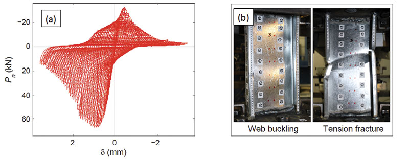
Figure 2: Cyclic axial load-deformation response in local buckling for 600S162-33.
OSB Sheathed Shear Wall Characterization
The CFS-NEES archetype building employs CFS-framed, OSB-sheathed shear walls. This is a common type, available in AISI-S213 for prediction of strength and stiffness. However, actual construction differs from the tests used to develop the AISI-S213 tables: shear wall sizes are not equal to 4-foot x 8-foot OSB panel, so numerous additional horizontal and vertical seams exist in actual shear walls; a large 0.097-inch thick x 12-inch deep carrier or ledger track blocks out the last 12 inches at the top of a shear wall; gypsum board is sheathed on the interior face of the wall; and, in some cases, the field studs are not the same thickness as the chord studs that frame out the shear wall. In addition, complete hysteretic response of the shear walls is not available, requiring the initiation of a test program and characterization effort.
Thanks to collaboration with the University of North Texas, the CFS-NEES project tested sixteen OSB-sheathed shear walls following the CUREE protocol (Figure 3); complete results are available in the test report and related papers. Strength degradation initiated at levels between 2% and 4% drift. Developed strength was in excess of AISI-S213 predictions, except in the case where shear wall field studs are thinner than the chord studs, a common practice for lightly loaded upper stories that should be accounted for in design. The addition of panel seams, ledger, and interior gypsum caused some divergence in stiffness predictions from AISI-S213 and may lead to greater than expected overstrength.
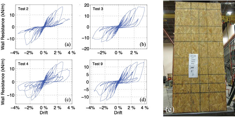
Figure 3. Hysteretic response of 1.22 m x 2.74 m OSB sheathed shear walls: (a) with ledger (b) gypsum board (c) baseline (d) extra vertical seam (e) front of Test 2.
Characterization of the test results was completed by determining parameters for one-dimensional (V-∆) phenomenological models employing the equivalent energy elastic-plastic (EEEP) model and the Pinching04 model. EEEP models are not appropriate for time-history analysis of these systems, only for pushover analysis. The Pinching04 models are utilized in the CFS-NEES building models as discussed under Full Scale Building Modeling.
“Fastener” Characterization
For CFS-framed, OSB-sheathed shear walls, the key energy dissipating mechanism occurs at the stud-fastener-sheathing connection. As the studs rack laterally, the fasteners tilt (and bend) as they bear into and damage the sheathing. Stiffness of the shear walls also relies on this same mechanism. In shear walls framed and sheathed with wood, it has been found that a similar mechanism dominates the response, and reasonable estimates of shear wall parameters can be derived directly from this local “fastener” response.
Characterizing this “fastener” response required a series of cyclic tests on stud-fastener-sheathing assemblies (Figure 4). The tests varied stud thickness, fastener spacing, and sheathing type. The direct shear response of the fastener assemblies is similar to the full walls, but even more pinched. Each test was characterized using the Pinching04 model, and complete results are provided in a CFS-NEES research report and a related paper. Work connecting the fastener response to the overall shear wall response is underway, and initial results indicate that with a little care – particularly with respect to hold-down flexibility – small-scale fastener tests have excellent predictive power for full-scale shear wall tests.
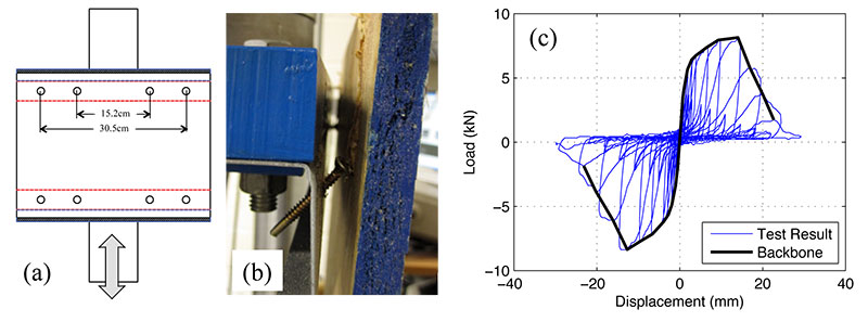
Figure 4. Fastener testing assembly: (a) front (b) side detail (c) typical response.
A lack of knowledge on the stiffness and cyclic response of typical connections in CFS goes beyond the details common in shear walls. As a result, as a companion to the CFS-NEES effort, a project was undertaken at Virginia Tech to understand the cyclic response of CFS connections more fully. The results provide a key building block for models of CFS assemblages and full buildings.
Full-Scale Building Modeling
The CFS-NEES full-scale building modeling effort has two major goals: (1) to provide a model that can meaningfully predict the CFS-NEES building response in order to understand the behavior of the building better and examine its response against a full suite of seismic excitations; and (2) to evaluate what level of model fidelity is necessary for engineers and researchers modeling buildings framed from CFS. Modeling the response of CFS buildings, even a particular CFS building, introduces an enormous number of potential assumptions. The project explored a complete model tree spanning from two-dimensional models with strength and stiffness based on specifications available to engineers, to three-dimensional models with shear walls based on direct experimental characterization and all steel framing explicitly modeled.
Research is still underway, but preliminary results indicate that a high degree of model complexity is required for developing observed system response. Consider a three-dimensional model with only shear walls included as rigid diaphragms (Figure 5a). The first-mode period, even using the experimentally calibrated shear wall stiffness, is 0.64 sec. In white noise testing, the same building with only shear walls in place has a first-mode period of 0.32 sec. An alternative model, with all wall framing explicitly included (Figure 5b), resulted in a much more accurate first-mode period of 0.38 sec. A key feature of this model is the inclusion of the full length ledger or carrier track, as well as the larger header members above openings. Work continues on several fronts with respect to the modeling: direct comparison with the full scale building testing, improving the complex model with a semi-rigid diaphragm, investigating how best to use models in engineering practice, and developing more robust reduced-order models for nonlinear time history analysis.
Figure 5. Three-dimensional OpenSees models of the CFS-NEES archetype building T=0.64 then 0.38 sec, where T=0.32 in the test: (a) shear walls only (b) shear walls and all gravity framing.
Full Scale Building Testing
In the summer of 2013, the project conducted full-scale tests on the CFS-NEES building at the NEES facility at the University of Buffalo. Two buildings were constructed; the first (Phase 1) had the complete lateral force resisting system sheathed, but otherwise all other gravity framing as bare steel (Figure 7a). After full-scale testing using the Canoga Park motion from the 1994 Northridge earthquake, this structure was dis-assembled and a second specimen (Phase 2) constructed. Testing examined the change in building response as a function of construction elements – gypsum, interior non-structural, etc. – as summarized in terms of shift in first-mode period (Figure 6). For Phase 2e (Figure 7c), the building was subjected to the Rinaldi ground motion, which is consistent with MCE-level spectral accelerations.
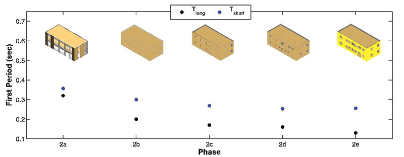
Figure 6. Shift in long- and short-direction first-mode period through construction phases: (a) LFRS and gravity steel only (b) exterior sheathed (c) inside face of exterior sheathed with gypsum (d) interior non-structural walls & stairs (e) exterior DensGlass sheathed.
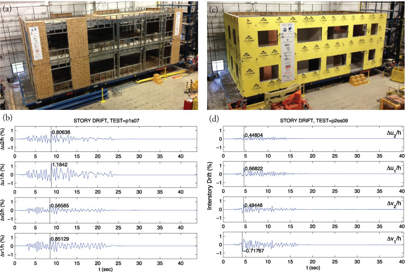
Figure 7. CFS-NEES Full-scale building testing and measured drift during seismic excitation: (a) Phase 1 completed building (b) Phase 1, story drift, Canoga Park (~DBE) (c) Phase 2e completed building (d) Phase 2e, story drift, Rinaldi (~MCE).
Under seismic testing, both the Phase 1 and Phase 2e buildings experienced minimal drift and returned to straight after excitation (Figure 7b,d). For the Phase 2e building, the story drift under Rinaldi was less than 1% and damage only occurred in the interior non-structural walls, largely confined to corners near openings. This full-scale testing provides the first look at the full system effect for buildings framed from CFS and is significant across the board: the building is stiffer and stronger than engineering designs suggest; the building responds as a system, not as a set of uncoupled shear walls; and the gravity system contributes to the lateral response. Overall performance for the tested building was far better than code minimums, and far better than advanced engineering models (e.g., Figure 5a), but not necessarily for well-understood reasons. Significant work remains to decipher the collected data fully.
Conclusions
CFS-NEES is providing a multi-prong effort to advance our understanding of seismic behavior and perform improved designs for structures framed from CFS. Significant progress has been made in hysteretic benchmarking and characterization at a variety of levels, from fastener, to member, to assemblages such as shear walls, as well as whole buildings. In addition, progress has also been made in predictive models, again across scales, that has potential for improved design. Full-scale testing of the CFS-NEES building provides a first look at the full system effect for buildings framed from CFS, which is significant across the board, requiring new approaches in prediction and design. Work remains to address details not fully explored (e.g., semi-rigid diaphragm behavior) and fully enable engineers working in this domain. For detailed reports and papers, visit www.ce.jhu.edu/cfsnees.▪